(TD) 4.11 ADC and DAC Conversion |

|

|
|
(TD) 4.11 ADC and DAC Conversion |
|
|
(TD) 4.11 ADC and DAC Conversion |
|
|
|
(TD) 4.11 ADC and DAC Conversion |
|
|
When working with multi-bit signals, changing radix or the msb/lsb performs a conversion similar to an Analog-to-Digital or Digital-to-Analog converter, depending on the direction that you are going in. For single-bit signals, like a digital waveform captured by a digitizing oscilloscope or from a SPICE simulation of a digital circuit, you can convert the analog data into digital data with uncertainty at the edges by using the Digitize Single Bit Signal button in the Analog Properties dialog of the signal.
ADC conversion on a multi-bit signal:
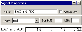
•Copy and paste the signal RealRadix_Digital using the CTRL-C and CTRL-V keys (this is the signal you drew in section 4.1). •Double click on the new signal's name so that the Signals Properties dialog opens, and name the signal DAC_and_ADC. |
|
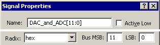
•Next, we will convert this analog signal to a multi-bit digital signal using a 12-bit ADC, by changing the MSB/LSB to 11-0, and the radix to Hex, and then pushing the Apply button. |
|
![]()
DAC conversion on a multi-bit signal:
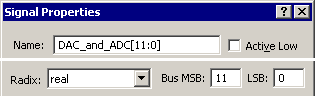
•Convert the digital signal, back to an analog signal by changing the radix to real and pressing the Apply button. |
|
![]()
•Notice that the values are no longer exactly 1.5 or 4.5. This is caused by the rounding errors of the 12-bit ADC. |
Save the timing diagram:
•Use the File > Save Timing Diagram to save your tutorial diagram. The next step will be loading a new diagram. |
ADC conversion on a single-bit signal:
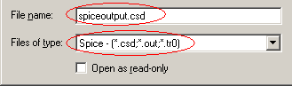
•Choose the File > Open Timing Diagram menu to launch the Open File dialog. Use the browse button to navigate to the SynaptiCAD > Examples > SPICE directory. This can also be accomplished using the Import/Export > Import Diagram menu which will allow selective loading of signals. |
•Choose a file type of Spice - (*.csd; *.out; *.tro). •Select the spiceoutput.csd file, and press the Open key load the file. |
|
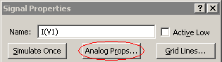
•Double click on I(V1) to open the Signal Properties dialog. Then press the Analog Props button to open that dialog. |
|
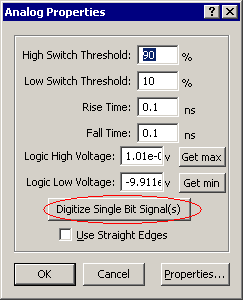
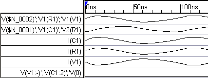
•Press the Digitize Single Bit Signal(s) button to digitize the signal. •Notice the waveform display now has two I(V1) signals. The I(V1)_d is the digitized version, and I(V1) preserves all of the analog data. You can alter the High Switch Threshold and Low Switch Threshold parameters to change the amount of uncertainty generated on the digital signal's edges. The Logic High and Low Voltage values should be set to the nominal high and low voltage values for the logic type of the digital signal. |
|
![]()