(TD) 1.4 Add the Signals |

|

|
|
(TD) 1.4 Add the Signals |
|
|
(TD) 1.4 Add the Signals |
|
|
|
(TD) 1.4 Add the Signals |
|
|
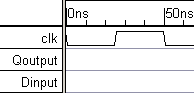
Next, add two signals and name them "Qoutput" and "Dinput".
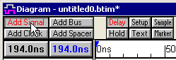
Use the Add Signal button to create new signals:
•Press the Add Signal button two times to add two signals to the diagram window. |
|
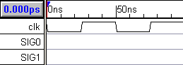
•The signals will have default names such as SIG0 and SIG1. |
|
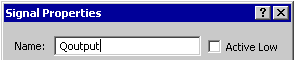
Double Click to rename the signals:
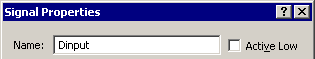
•Double click on the SIG0 signal name to open the Signal Properties dialog. •Enter Qoutput into the Name edit box. (DO NOT CLOSE THE DIALOG) |
|
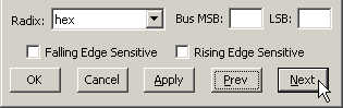
•Click the Next button or ALT-N to move to the next signal on the list. Notice that SIG1 is now displayed in the Name edit box. |
|
•Enter Dinput into the Name edit box and press the OK button to close the dialog. |
|
•The timing diagram should look like the following. |
|
Tip: The Signal Properties dialog is a modeless dialog - you can keep the dialog open while working with other drawing features. The Boolean Equation and Simulation features of the Signal Properties dialog are covered in the Simulated Signals tutorial.