(TD) 1.9 Add the Inverter Propagation Delay |

|

|
|
(TD) 1.9 Add the Inverter Propagation Delay |
|
|
(TD) 1.9 Add the Inverter Propagation Delay |
|
|
|
(TD) 1.9 Add the Inverter Propagation Delay |
|
|
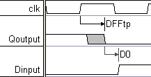
Next add the delay that represents the propagation time of the inverter from its input Q to its output D. Since this delay is the second in a chain starting with DFFtp, its uncertainty region will be larger than just the uncertainty caused by the inverter.
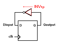
Add the Inverter Delay:
•Make sure the Delay button is red so that right clicks will add delays. |
|
•Left click on the first falling edge of the Qoutput signal to select it (the same edge that ends the "DFFtp" delay). •Right-click on on the first rising edge of the Dinput signal to add a blank delay. |
|
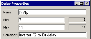
•Double-click on the new delay to open the Parameter Properties dialog and enter the following values: Name is INVtp, propagation delay of 3 to 11 ns, and a comment of Inverter (Q to D) delay. •Click on the OK button to close the dialog. |
|
Verify that the Uncertainty region is correctly calculated:
Notice the uncertainty region for the Dinput transition is much larger than the 3-11 ns that you entered in the last step. This is because the DFFtp uncertainty adds to the INVtp uncertainty.
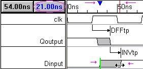
•Click on the first rising edge of Dinput (to select it). This also moves the blue delta mark on the time line. •Move the mouse cursor over the second edge of the uncertainty region. As you move the red line on the time line tracks your progress, and the Blue delta readout shows the exact distance from the blue delta mark. |
|
•Here the readout shows that the uncertainty region lasts for 21ns (13ns from DFFtp + 8ns from INVtp = 21ns). |
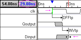
•Next, click on the first edge of clk and measure to the end of the uncertainty region of Dinput. If both the inverter and the D flip-flop are slow, Dinput may not transition until 29ns after the clock edge. |
|