(Compare) 11: Adjust the Time Difference Between Two Diagrams |

|

|
|
(Compare) 11: Adjust the Time Difference Between Two Diagrams |
|
|
(Compare) 11: Adjust the Time Difference Between Two Diagrams |
|
|
|
(Compare) 11: Adjust the Time Difference Between Two Diagrams |
|
|
The time difference between two timing diagrams can be easily adjusted using the Edit Waveform Edges dialog. In this section we will compare two diagrams that are slightly offset in time.
Compare the two data sets:
•Select the File > Open Timing Diagram From menu and load the original analyzerData.txt file located in the SynaptiCAD\Examples\TutorialFiles\WaveFormComparison directory. Don't forget to set the file type to Test Vector Spreadsheet/Tektronix (*.txt). Note: If you accidentally saved over this file during a previous step, simply delete all the signals except the three Test reference signals, change the names back to dots instead of underlines, and change the valid state on pin2 to a high state. •Select the File > Compare Timing Diagram menu option and select the simulationResults_offset.btim to load the file and perform a compare. |
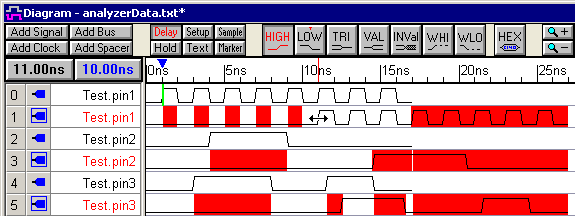
•Notice that all three of the compare signals have a longer starting segment than their counterparts. This causes much of the diagram to show as differences, when in reality the two data sets have a time offset. •Use the mouse and the time readout buttons to determine the amount of time that the diagram is offset from the other (10 ns). Also double click on an edge to open the Edge Properties dialog and find the exact times of edges. |
To modify the time difference between two diagrams:
The offset time can either be removed from the compare signals or it can be added to the reference signals. In this tutorial the offset will be removed from the compare signals because the SET ALL button makes it easy to select the compare signals.
•Select all the compare waveforms by pressing the SET ALL button. This also opens the Signal Properties dialog in group editing mode, but we will not be using it so you can close the dialog. |
|
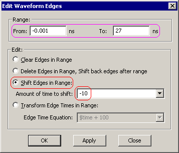
•Select the Edit > Edit Waveform Edges menu option to open the Edit Waveform Edge dialog. •Notice that the time range is the entire timing diagram. •Select the Shift Edges in Range radio button. •Enter -10 into the Amount of time to shift edit box. The time unit, ns, in implied by the display time unit of the diagram. •Press OK to shift the selected waveforms and close the dialog |
|
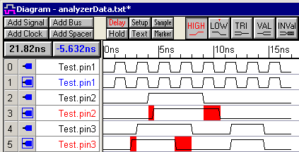
•Press the compare button to perform another compare. |
|
Tip: The Edit Waveform Edges dialog can also be used to perform frequency multiplication. See the Timing Diagram Editors manual Section 1.7: Editing Waveform Edges from an Equation for more information on this dialog.