(TD) 2.3 Boolean Equations with Delays |

|

|
|
(TD) 2.3 Boolean Equations with Delays |
|
|
(TD) 2.3 Boolean Equations with Delays |
|
|
|
(TD) 2.3 Boolean Equations with Delays |
|
|
Next we will modify the Boolean equation to take into account the propagation delay through the AND gate. First we simulate a simple 15ns delay, then we will simulate a min/max delay. The SynaptiCAD delay operator takes a signal on the left, and a time or parameter name on the right, and returns a signal. If a parameter name is used on the right hand side of the delay operator, then the equation will simulate true min/max timing. This true min/max timing is the main advantage that SynaptiCAD's format has over the VHDL or Verilog format.
Simulate a simple delay:
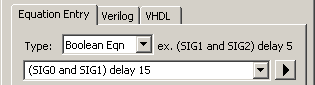
•Add a 15ns delay to the SIG2 Boolean equation. The box accepts Verilog, VHDL, or SynaptiCAD syntax, so these equations are all equivalent to each other. •Press the Apply button at the bottom of the dialog to notify the simulator about the change in the equation. |
#15 (SIG0 & SIG1) (SIG0 and SIG1) after 15 (SIG0 and SIG1) delay 15
|
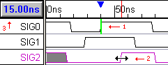
•Verify that SIG2 is 15ns delayed, by first selecting an input edge then moving the mouse over the resulting edge on SIG2. The blue delta read out will say 15ns. |
|
Simulate a true min/max delay using SynaptiCAD syntax:
The most powerful feature of a timing diagram editor is the ability to display min/max timing using the grey uncertainty regions. To make the Simulated Signals support min/max timing, we created the SynaptiCAD delay operator, because the delay operators in VHDL and Verilog only support a single delay.
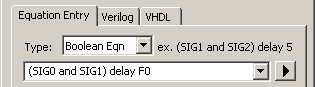
•Edit the equation so that the delay references the free parameter F0 then press the Apply button to notify the simulator about the change in the equation. |
|
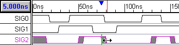
•Notice that SIG2 has grey uncertainty regions that are 5ns wide (F0.max - F0.min). |
|
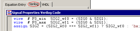
View the HDL code that models the Boolean equation:
The timing diagram editor takes the Boolean equation and generates Verilog or VHDL code necessary to perform the equation. You can edit this code directly to perform more complex functions. The tool ships with an embedded Verilog simulator that executes the code, so if you change VHDL code you will have to provide the tool with a VHDL simulator. The manual explains how to configure for a different simulator.
•Press the Verilog tab to open an editor window that displays the generated Verilog code. Do not change the code now. |
•This example demonstrated true min/max simulation, however Min-Only and Max-Only simulations can be performed by changing the selection in the Timing Model drop-down list of the Simulation Preferences dialog box. The Simulation Preferences dialog can be opened using the Options > Diagram Simulation Preferences menu option. The Timing Model drop-down list is in the upper right corner. |