(Compare) 4: Compare Timing Diagrams |

|

|
|
(Compare) 4: Compare Timing Diagrams |
|
|
(Compare) 4: Compare Timing Diagrams |
|
|
|
(Compare) 4: Compare Timing Diagrams |
|
|
When comparing two files, the file that is being compared/merged into the reference diagram must be a SynaptiCAD btim file. However, since WaveFormer reads many different file formats, it is a simple operation to translate a waveform file to .btim. In this step we will first convert a VCD (Verilog simulation file) into a .btim file. Then we will use the converted file to compare against a logic analyzer file. This shows how a simulation file could be compared with data captured from an actual circuit.
Import the VCD file and save it as a BTIM file:
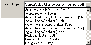
•Select the Import/Export > Import Timing Diagram From menu to open a special version of the Open Timing Diagram dialog that remembers the file type of the last file imported. •Select the Verilog Value Change Dump (*.dump, *.vcd) option from the File of Type list. This is a file generated by a Verilog simulator. |
|
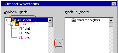
•Select the simulationResults.vcd in the SynaptiCAD\Examples\TutorialFiles\WaveFormComparison directory. •Press Open to close the file dialog and launch the Import Waveforms dialog. This dialog allows you to selectively load signals from really large files. |
•Select the All Signals folder in the Available Signals side of the dialog by left clicking on it. •Press the right arrow button to place these signals in the Signals to Import tree. •Press OK to close the dialog and import the signals. |
|
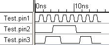
•Use the Zoom In button to get a better view of the changing signal edges. •Choose the File > Save Timing Diagram As menu to open the Save File dialog. •Choose Timing Diagram - Binary (*.btim) from the type drop-down and save the file as simulationResults.btim. |
|
Load the Logic Analyzer Data file:
Next we will open a data file that is in a Spreadsheet format similar to that generated by a Tektronix logic analyzer.
•Select the File > Open Timing Diagram From menu to open the File dialog. We are opening the file this way just to skip the Import Waveforms dialog step that was demonstrated with the VCD file load. •Select the Test Vector Spreadsheet/Tektronix (*.txt) option from the File of Type list. •Select the analyzerData.txt in the SynaptiCAD\Examples\TutorialFiles\WaveFormComparison directory. •Use File > Save Timing Diagram as menu to save the file as my_analyzerData.txt |
Compare the diagrams:
When two diagrams are compared, the signals from the second diagram selected are brought into the first diagram as compare signals. These signals can either be grouped at the bottom of the open diagram or the Compare signals can be ’interleaved’ with the original signals. That is, the Compare signal for a given original signal will be inserted directly under the original signal. This behavior is controlled using the View > Compare and Merge > Interleave Compare and Merge Signals menu option. This tutorial will have the interleave feature turned on.
•Select the File > Compare Timing Diagram... menu option to launch the Compare dialog. Notice that the default file type is Timing Diagram (*.tim, *.btim). •Select the simulationResults.btim file that you converted earlier in this section. •Click Open to compare the two diagrams. |
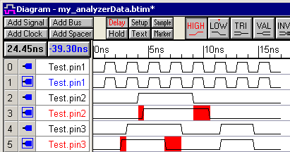
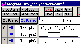
•Notice that the Compare signals are placed immediately following the signals that they are being compared to since the Interleave Compare and Merge Signals option is on. •Notice that two of the signal labels, Test.pin2 and Test.pin3, have turned red because there are differences on these signals. |
Tip: If the data sets being compared have slightly different naming schemes, then the signals will not properly interleave because the program will not be able to properly match the signals for comparison. The Edit > Search and Rename Signals feature is handy for modifying one of the sets of signal names in the case. This feature performs pattern matching on the signal names and allows you to replace characters in the name, or append/remove a prefix or a suffix to the signal name. We will demonstrate this in Section 9 of this tutorial.