(TD) 1.13 Drawing Virtual Buses |

|

|
|
(TD) 1.13 Drawing Virtual Buses |
|
|
(TD) 1.13 Drawing Virtual Buses |
|
|
|
(TD) 1.13 Drawing Virtual Buses |
|
|
Buses are multi-bit signals. The timing diagram editor supports several different kinds of buses to accommodate all the different ways signal information may be imported or exported from the tool. Virtual and Group buses have the ability to be converted from one to the other type by right clicking on the name.
•Virtual Bus is a single signal defined as multiple bits. This is the most common and easiest to work with because all of the normal signal editing techniques work on it. •Group Bus displays the aggregate values of its member signals. This is handy way to manage lots of single bit signals that have been imported from other sources (like logic analyzers). •Simulated Bus is a simulated signal defined as a concatenation of it member signals. This is primarily designed for the testbench products so that both a member signal and the whole bus can be passed to models as needed. This is covered in the Simulated Signals Tutorial. •Differential Signals are two-bit group buses that display a superimposed image of the member signal waveforms. This can also be a useful technique for overlaying two analog signals to compare them visually. |
Draw a Virtual Bus:
Virtual Buses are the recommended way to display and work with bus information. Virtual Buses are regular signals that have the LSB and MSB values set.
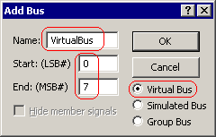
•Add an 8-bit virtual bus named VirtualBus with an LSB of 0 and an MSB of 7 using one of the following methods. |
•Fastest method: Make sure no signals are selected, then click the Add Bus button to open the Add Bus dialog. Then select the Virtual Bus radio and set the MSB and LSB values. •Alternate method: Add a signal and then double-click on the name to open the Signal Properties dialog. In the dialog edit the edit the MSB and LSB values. |
|
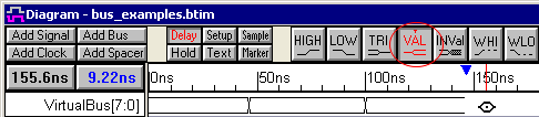
•You can sketch the virtual bus waveform using any of the graphical states, but normally virtual buses are drawn with all valid states. Press the Valid state button twice so that it is red and also has the red T on the top of the button. Then draw some consecutive valid states. |
•Open the Edit Bus State dialog by either double-clicking on a segment OR first selecting a segment and then clicking the HEX button on the button bar. |
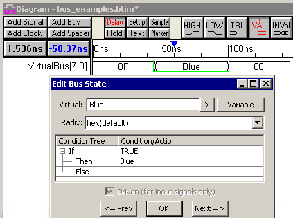
•In the Virtual field, type in the segment value. This can by any type of data including text with spaces (e.g., A0C, 5 + 3, blue level, and 24 are all valid virtual states). •Use Next and Prev buttons, or the <Alt>-N and <Alt>-P keys, to move between the different segments on the same bus. When you are done press the OK button to close the dialog. |
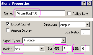
Investigate the Virtual bus using the Signal Properties dialog:
•Double click on the VirtualBus signal name to open the Signal Properties dialog. •On the bottom of the dialog, notice the MSB and LSB settings are the same as what you typed in the Add Bus dialog •Notice the Radix setting which controls how the tool interprets the data in the virtual states of the waveform. |
|