(TD) 2.9 Behavioral HDL Code |

|

|
|
(TD) 2.9 Behavioral HDL Code |
|
|
(TD) 2.9 Behavioral HDL Code |
|
|
|
(TD) 2.9 Behavioral HDL Code |
|
|
In addition to the simulation of Boolean and registered logic circuits, SynaptiCAD products can simulate behavioral Verilog code, and if you provide a VHDL simulator it can also simulate behavioral VHDL code. The behavioral code is entered directly into the Verilog or VHDL tabs in the Signal Properties dialog, instead of using the Equation Entry tab that we used for the Boolean equations in the last sections. There is also a template feature that generates code from a Boolean equation and allows you to modify the generated code.
In this section we will use a register template as a starting point to build a circuit that asynchronously counts the number of edges that occur on SIG1 and synchronously presents the total number of edges on the positive edge of the clock.
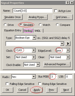
Use a partially defined signal to generate PLACEHOLDER code:
•Add a new signal named Count. •Select the Simulate type setting. •Set the clock to CLK0 with an edge/level of pos. •Set the MSB to 3. •Press the Apply button to apply the changes and generate the code. Since there is no Boolean equation for the signal, this is also going to generate a compile error and all the simulated signals in the diagram will go grey. If no compile error happens, then choose Options > Diagram Simulation Preferences menu and check the Continuously Simulate box.
|
|
•Next, press the Verilog tab to open an editor window containing the the template code. The internal wire names Count_wf*** will vary depending on how many signals you have simulated. |
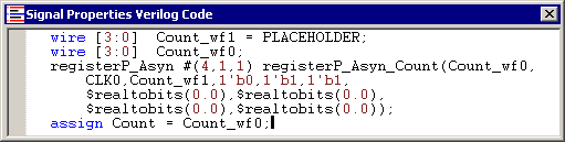
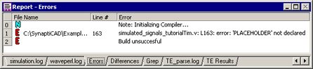
•The registerP_Asyn line instantiates (defines an instance of) a 4 bit positive-edge-triggered register of the type used by the logic wizard. This register takes PLACEHOLDER as an input and outputs a synchronized version on Count. •The auto generated variable PLACEHOLDER is undefined and will not simulate. If a Boolean equation was defined for the circuit, it would replace the PLACEHOLDER variable. This error will be displayed in the Report window under the error tab. |
Add behavioral code to the generated code:
We will use the PLACEHOLDER variable to store the edge count. First we will define PLACEHOLDER, give it an initial starting value, then define an always process that triggers each time the SIG1 changes. Since Count is buffered by a positive edge triggered register, it will not display the PLACEHOLDER value until the positive edge of the clock.
•Either copy-and-paste or type the first four lines the below code directly into the Signal Properties Verilog Code window (add the bold lines): |
reg [3:0] PLACEHOLDER;
initial PLACEHOLDER = 0;
always @(SIG1)
PLACEHOLDER = PLACEHOLDER + 1;
wire [3:0] Count_wf1 = PLACEHOLDER;
wire [3:0] Count_wf0;
registerP_Asyn #(4,1,1) registerP_Asyn_Count(Count_wf0,
CLK0,Count_wf1,1'b0,1'b1,1'b1,
$realtobits(0.0),$realtobits(0.0),
$realtobits(0.0),$realtobits(0.0));
assign Count = Count_wf0;
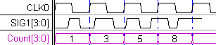
•Click the Apply radio button. Verify that Count is counting the edges of SIG1. The new edge count is presented on each positive edge of CLK0. The Count starts at one because there is a 1'bz to 1'b0 transition at time zero on SIG1. |
Code explanation:
The code that you just entered is behavioral Verilog code.
•The first line defines PLACEHOLDER as a 4-bit register. PLACEHOLDER needs to be defined as a register rather than a wire in this case because it must "remember" its value. Verilog wires don't remember their values so they must be constantly driven to retain their value. •The second line initializes the value of PLACEHOLDER to 0 when the simulator first runs. •The third and fourth lines contain an always block (note for VHDL users: these work like VHDL process blocks). Whenever SIG1 changes state, the always block will execute, incrementing PLACEHOLDER. •The rest of the lines consist of the automatically generated template code that instantiates the synchronizing register. |