(TD) 2.1 Setup for Simulation |

|

|
|
(TD) 2.1 Setup for Simulation |
|
|
(TD) 2.1 Setup for Simulation |
|
|
|
(TD) 2.1 Setup for Simulation |
|
|
In the next few sections we will simulate signals using Boolean and registered logic equations. The inputs to a simulated signal are other drawn signals, so in this section we will create a timing diagram and a free parameter that we will use in the subsequent steps.
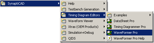
Run WaveFormer Pro or higher:
•Run WaveFormer Pro, DataSheet Pro, VeriLogger, or one of the more advanced products. If you are evaluating Timing Diagrammer Pro or one of our Viewers and you would like to learn about the simulation features, close the program and restart the evaluation version in WaveFormer Pro mode. |
Create a Timing Diagram:
•Choose File > New Timing Diagram menu to open an empty timing diagram window. |
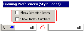
•Hide the direction and index columns in the diagram window by choosing Options > Drawing Preferences to open the dialog. Then uncheck Show Direction Icons and Show Index. |
|
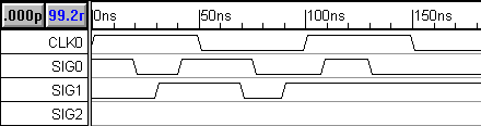
•Sketch the following timing diagram. Clock CLK0 has the default 100ns period. Just approximately sketch the waveforms for SIG0 and SIG1; exact edge placement is not necessary for this tutorial. Leave SIG2 blank, because it will be the simulated signal. |
Create a Free Parameter:
We will also be experimenting with the min and max timing features of the Boolean equations, so create a Free Parameter to use in the equations.
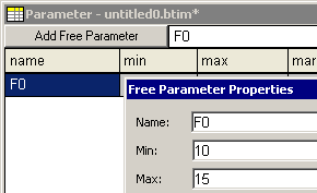
•In the Parameter window, press the Add Free Parameter button to add a free parameter F0. |
|
•Double-click on F0 to open the Parameter Properties dialog. •Enter a min time of 10, and a max time of 15, then press the OK button to close the dialog. |
|