(Compare) 9: Mask Sections to Exclude Comparison |

|

|
|
(Compare) 9: Mask Sections to Exclude Comparison |
|
|
(Compare) 9: Mask Sections to Exclude Comparison |
|
|
|
(Compare) 9: Mask Sections to Exclude Comparison |
|
|
It is sometimes useful to mask some segments during comparison. In this example, we will create a Compare_Enable signal that will specify the specific clock segments over which we want the comparison to be performed. Then we will use a Boolean equation (Offset_Clock and Compare_Enable) in a simulated signal to define the region in which to perform the compare. Since this step uses simulated signals you will need to be using a product that supports this feature like WaveFormer Pro (not one of the Viewers).
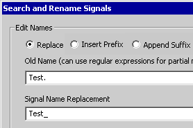
Search and Replace Signal Names:
First, we will change the names of the signals in the diagram so that when we add the simulated signal, we do not get simulation errors (with the signal names Test.* the simulator will look for a module that we will not have defined).
•Press <CTRL>A to select all of the signals in the diagram. The Search and Rename signals feature will search the selected signals. If no signals are selected, then a dialog will appear asking if you would like to select all signals in the diagram. |
•Select the Edit > Search and Rename Signals menu option to open the Search and Rename Signals dialog. •Enter Test. in the Old Name edit box. •Enter Test_ in the Signal Name Replacement edit box. •Click OK to close the dialog and rename the signals. |
|
Add the Compare Enable Signal:
•Add a new signal called Compare_Enable and draw the following waveform that is high between 4ns and 8ns |
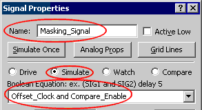
Add the Simulated Masking Signal
Next, place a simulated signal in the diagram to use as the clocking signal for the comparison:
•Add a signal to the diagram and set the following properties in the Signal Properties dialog: •Set the Name to Masking_Signal. •Select the Simulate radio button (instead of Drive). •Enter Offset_Clock and Compare_Enable in the Boolean Equation edit box. |
|
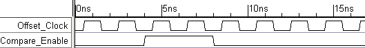
•Press the Simulate Once button to generate the simulated signal. |
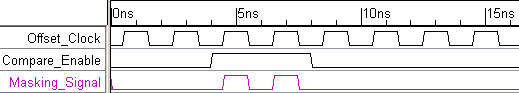
•Notice that the masking signal is high only during the times that both the Compare_Enable and the Offset_Clock are high. These are the clock segments that are not masked. The comparison will be performed during these segments. |
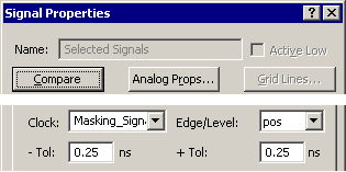
Use the Masking Signal to Mask Clock Segments
Next we will edit the compare signals so that they use the new Masking_Signal as a clock.
•Either press the SET ALL button or choose the View > Compare and Merge > Edit Compare Signals menu to select all the compare signals and open the Signal Properties dialog. |
|
•Set the Clock to Masking_Signal. •Click Compare to apply the changes and perform the comparison. |
|
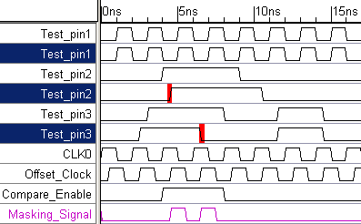
•Notice that the first and last differences that were previously in the diagram have now disappeared, because they are masked from the comparison. |