(TD) 6.10 Modeling the Incrementor and Latch Circuit |

|

|
|
(TD) 6.10 Modeling the Incrementor and Latch Circuit |
|
|
(TD) 6.10 Modeling the Incrementor and Latch Circuit |
|
|
|
(TD) 6.10 Modeling the Incrementor and Latch Circuit |
|
|
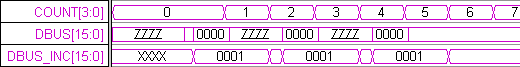
In Section 3 we used the Boolean Equation interface to model the state machine using negative edge-triggered registers. Now we will use the same interface to generate level-triggered latches used to model the increment-and-latch circuit. The value stored in the SRAMs is placed on DBUS and the incrementor circuit takes that value, adds one to it, and latches the incremented value:
1. Create a new signal called DBUS_INC.
2. Enter the following equation into the Boolean Equation edit box: DBUS + 1
3. Choose the READ signal from the clock drop-down list box.
4. Choose high from the Edge/Level drop-down list box. This selects the type of latch to be used.
5. Set Radix to hex, MSB to 15, and check the Simulate radio button.
6. Press the Simulate Once button and verify that DBUS_INC is an incremented version of DBUS. If DBUS_INC did not simulate, use the methods in section 4 to determine the error.