(TD) 2.6 Multi-bit Equations |

|

|
|
(TD) 2.6 Multi-bit Equations |
|
|
(TD) 2.6 Multi-bit Equations |
|
|
|
(TD) 2.6 Multi-bit Equations |
|
|
The Interactive Simulator can automatically generate multi-bit equations for the register, latch and combinatorial logic circuits. To convert a register or latch circuit into a multi-bit signal, change the MSB of the input signal and the MSB of the register or latch. If the sizes of the signals do not match, WaveFormer maps as many LSB's as it can. The following example uses only a simple equation to demonstrate the LSB mapping feature, however multi-term Boolean equations are completely supported.
Create a Multi-bit Signal by changing the MSB setting:
•Create a copy of SIG2. Click on the SIG2 name in the Label window to select it. Select the Edit > Copy Text and Signals menu option to copy the signal, then the Edit > Paste option to paste the signal. There are now two signals named SIG2 in your diagram. |
|
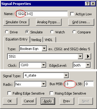
•Double click on the bottom SIG2 to open the Signal Properties dialog, and rename the signal to SIGX. •Type 3 in the Bus MSB edit box. This will make SIGX a 4-bit signal and add a [3:0] to the end of the name. •Press the Apply button to notify the simulator of the changes. |
|
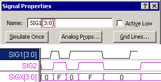
•SIGX's waveform is now drawn as a bus with a 4 bit binary display. Only the LSB of SIGX is working because the input signal SIG1 is a single bit. Compare SIG2 and SIGX and verify that they are the same values. |
|
Change the input signal to a multi-bit signal:
•Double-click on SIG1 to open the Signal Properties dialog, and add [3:0] to the end of the name. This has the same effect as changing the values in the MSB and LSB edit boxes. •Press the Apply button. Now all four bits of SIGX should be toggling between 0 and F. If the radix is in Binary, the signal will toggle1111 and 0000. The radix box is located in the lower left part of the dialog. |
|
•If you want to further experiment with multi-bit signals, change SIG1's graphical segments to Valid regions instead of Highs and Lows. Then double click on a valid region to open the Edit Bus State dialog box. Type different hex values from 0 through F, like 5 or A, into the Virtual edit box and watch how it affects the output of SIGX and SIG2. Since SIG2 is a single bit signal it uses only the LSB of the input signals. |