(TD) 4.1 Viewing Analog Waveforms |

|

|
|
(TD) 4.1 Viewing Analog Waveforms |
|
|
(TD) 4.1 Viewing Analog Waveforms |
|
|
|
(TD) 4.1 Viewing Analog Waveforms |
|
|
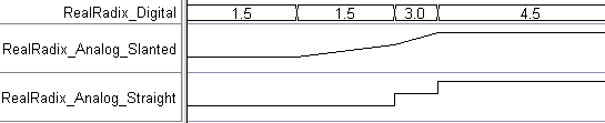
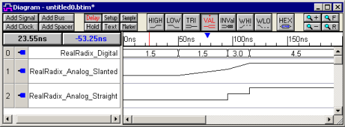
In this section you will draw the timing diagram shown below. Each of the three signals have the same waveform values, but are displayed using different settings. The first analog signal draws the waveform from point to point in a piecewise-linear way. The second analog signal shows the waveform drawn as step voltages.
Add Two Digital Signals that are exactly the same:
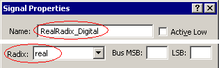
•Add one signal by pressing the Add Signal button. •Double click on the signal to open the Signal Properties dialog. •Change the name to RealRadix_Digitaland choose the real radix from the radix box. •Close the dialog. |
|
•Next, sketch four valid segments as shown. •Then double click on the first segment to open the Edit Bus State dialog and enter a Virtual state of 1.5. Use the Next button in the dialog to jump to subsequent segments and change the values to 1.5, 3.0, and 4.5. Close the dialog when you are done. |
![]()
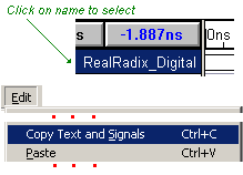
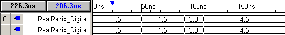
•Copy the completed digital signal by selecting the signal name then choosing the Edit > Copy Text and Signals menu. Then Paste it using the CRTL-V keys so that you have two identical signals. |
|
Setup the Analog Display for the default Slanted Display:
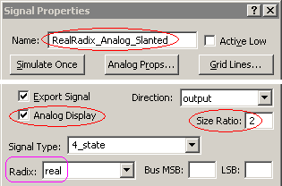
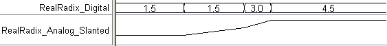
•Double click on the new signal to open the Signals Properties dialog and change its name to RealRadix_Analog_Slanted and check the Analog Display box so that the signal will display as a magnitude plot. •By changing the Size Ratio to 2 or larger, the signal will be drawn taller so that it is easier to see the waveform. •Close the dialog to display the signal as an analog magnitude plot. |
|
Display the signal as step voltages:
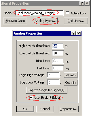
•Copy and Paste the RealRadix_Analog_Slanted signal by selecting the name and using the Ctrl-C and Ctrl-V keys. •Double click on the new signal to open the Signals Properties dialog and change its name to RealRadix_Analog_Straight. •Since this is a copy of the other analog signal, the Analog Display is checked and the Radix is set to real. •Next press the Analog Props button to open the Analog Properties dialog. •Check the Use Straight Edges box to change the magnitude display. Press Ok to close this dialog. •Notice when the steps occur in relation to the RealRadix_Digitial signal. |
|