(SDC) 6: Add Delays to Inputs |

|

|
|
(SDC) 6: Add Delays to Inputs |
|
|
(SDC) 6: Add Delays to Inputs |
|
|
|
(SDC) 6: Add Delays to Inputs |
|
|
In order for input signals to be properly clocked into the design, we must tell the synthesis tool how much delay has been added to input signals by external logic relative to our clocking signal. In other words, the timing analyzer for the synthesis tool can only extract part of the timing path for any timing path that begins on an input to the design, so the missing part must be given to it by a set_input_delay constraint.
In the histogram circuit, the ADC's Data and Valid signals are inputs to the FPGA. From the ADC's data sheet you would find the delay values relative to the clock signal.
For single-bit signals, like ADC_VALID, there will usually be different values for Low-to-High and High-to-Low transitions so it is important to look for that. For buses such as ADC_DATA, there is usually only one delay specified that represents the longest of the L-H or H-L transition times. In this section we will add 4 delays from the derived clock to the transitions of Data and Valid. Then we will enable SDC code generation for these delays.
Specify External Delays to Inputs of your Design:
•Press the Delay button so that right clicks will add delays. |
|
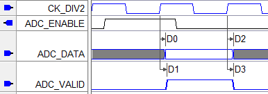
•Left click on the CK_DIV2 rising edge at 200ns to select it. This edge will be the first or driving edge of the delay. •Right-click on the ADC_Data transition near 200ns to add the delay between the two edges. This is the edge that will be forced by the delay. |
|
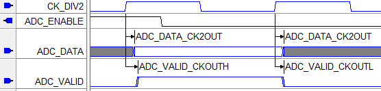
•Add three more delays as shown. •Double click on each delay and enter the names and min/max times for each delay. |
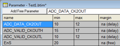
D0 & D2 = ADC_DATA_CK2OUT (10,12) D1 = ADC_VALID_CKOUTH (15,17) D3 = ADC_VALID_CKOUTL (10,12) |
•Notice that the delay names are also added to the Parameter window. |
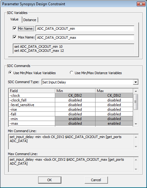
Enable SDC Code Generation:
•Double click on a delay to open the Delay Properties dialog and press the SDC Code button to open the Parameter Synopsys Design Constraint dialog. •Create two SDC variables by checking Min Name and Max Name checkboxes. The two new variables will display in the display area below the checkboxes. •Create two SDC commands by changing the SDC Command Type from None to Set Input Delay. The two new SDC commands will display in the area below the SDC command parameters grid. Note that the generated SDC commands reference the Min/Max SDC variable names created in the previous step. •The command parameters grid can be used to set optional parameters to the SDC commands, but this is generally not necessary. Gray fields in the options grid indicate parameters that are computed from the delay timing parameter's data, so only the white fields can be edited. |