4.1 Boolean Equations with Delays |

|

|
|
4.1 Boolean Equations with Delays |
|
|
4.1 Boolean Equations with Delays |
|
|
|
4.1 Boolean Equations with Delays |
|
|
Signals can be defined using a Boolean equation of other signals in the diagram. The embedded simulation engine properly simulates multi-bit signals. The simulator also uses true min/max timing models so that the resulting simulated signals can propagate uncertainty delay through the timing diagram.
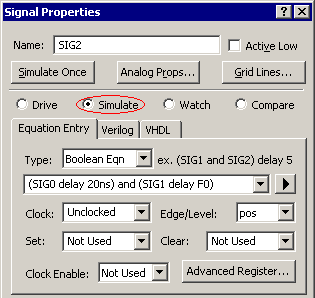
Creating a Simulated Signal:
•Double click on a signal name to open the Signal Properties dialog. •Select the Simulate radio button to allow the signal to be re-simulated each time an input signal is changed. •Enter a Boolean equation and check any other attributes for the simulation. Section 4.2 covers the Clock and Register features. •The signal will start to simulate as soon as an equation is entered and it will draw purple waveforms on the simulated signals. If the waveform is grey there is an error in the equation, see the error section below. |
|
Syntax
The Boolean Equation edit box accepts Boolean equations in VHDL, Verilog, and SynaptiCAD's enhanced equation syntax. All signal names are case sensitive.
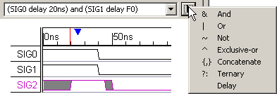
•The quick fill box contains all of the SynaptiCAD operators. •The delay operator takes a signal on the left and a time or parameter name on the right. If a parameter is entered then the equation will simulate using true min/max timing and puts grey uncertainty regions on the simulated signal. |
|
•The delay operator can also be made to simulate min-only or max-only simulations by selecting the Options > Diagram Simulation Preferences menu to open the dialog and then choosing the appropriate setting from the Timing Model list.
Below are some examples of Boolean equations:
•A 3-input AND gate with a no delay |
SIG0 and SIG1 and SIG3 |
•A 3-input AND gate with a 20ns delay |
(SIG0 and SIG1 and SIG3) delay 20ns |
•A 2-input AND gate using a delay parameter to define the delay time. Each edge of the simulated signal will have a gray uncertainty region that is the difference between the min and max times of GateDelay. |
(SIG0 and SIG1) delay GateDelay |
•A Tristate Gate |
EnableSig ? SIG0 : 'bz |
•A 2-1 MUX |
S0 ? SIG0 : SIG1 |
•A 4-1 MUX |
S1?(S0?SIG0:SIG1):(S0?SIG3:SIG2) |
•Signal Concatenation (Note: the simulated signal must have a proper MSB size to handle the result) |
{SIG0, SIG1} |
•Concatenate bit slices |
{SIG0[3:0], SIG1[7:4]} |
Multi-bit Simulation is Automatically supported
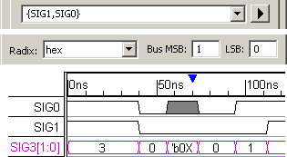
•Set the MSB and LSB in the Signal Properties dialog to model multi-bit simulated signals. • If a signal has a non-binary radix, and one of the bits on that signal is in an unknown state (X), then that segment will be displayed as a binary value. |
|
•For example in the picture, SIG3 has a radix of hex and most of the value are displayed in hex. However, one of the segments has an unknown state, and that state is displayed in binary since 'b0X is not a valid hexadecimal value.
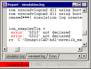
Errors
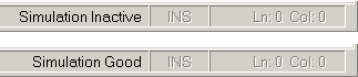
There is an error status bar on the bottom right of the big window.
•Simulation Inactive means that there are no signals with the type Simulate |
|
•Simulation Good shows that all equations are simulating without errors
•Compile Error shows that something is wrong with an equation. •The Simulation.log file displayed in the Report window shows simulation results and any simulation errors. •The Error tab shows simulation errors in a condensed tabular form. |
|
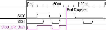
Stopping a Simulation with an End Diagram Marker
By default, simulations run to the end of the last drawn signal in the timing diagram. If the inputs to a particular signal are not drawn all the way to the simulation end time, then their last state value is maintained until the end of the simulation.
•To force the simulation to stop at a specific time, add a Marker to the diagram and set its type to be End Diagram. See Section 6.4: Marker Lines. |
|
Use care when attaching graphical parameters to a simulated signal:
When a Boolean equation is re-simulated, the signal's waveform is cleared of event edges. The program attempts to preserve the attachment of parameters and text objects on signal edges, but the addition or loss of edges during the re-simulation may move these objects.
Partially Simulated Signals:
Sometimes it is useful to use an equation to draw the initial waveform, then return it to a "drawn" waveform that allows manual editing.
•To simulate once, enter an equation, leave the button on Drive, and press the Simulate Once button. This will simulate the waveform using the current inputs but the waveform will be black to indicate it can be edited.