8.2 Waveform Equation Blocks for editable Analog waveforms |

|

|
|
8.2 Waveform Equation Blocks for editable Analog waveforms |
|
|
8.2 Waveform Equation Blocks for editable Analog waveforms |
|
|
|
8.2 Waveform Equation Blocks for editable Analog waveforms |
|
|
Sine, Capacitor, Ramp and Exponential waveforms can be inserted into a waveform segment using a Waveform Equation Block. Unlike the State Label equations of the next section which append analog waveform segments onto the end of a signal, waveform equation blocks can edited after they are created. For this reason, it's often better to use a waveform equation block rather than a State Label equation.
Overview of steps to add a Waveform Equation Block to a Signal
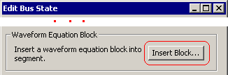
•Double click on a segment in the waveform to open the Edit Bus State dialog. |
|
•Press the Insert Block button to open the open the Waveform Equation Block Properties dialog. |
|
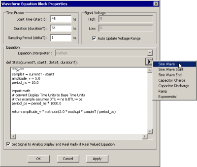
•Use the fly-out to pick one of the preprogrammed analog waveforms or write your own Python function. •Notice that you can edit the period and amplitude directly in the Python code. •The fields of this dialog are described below in the Programming Waveform Equation Blocks sub-section. •Press OK to exit this dialog and then close the Edit Bus State dialog. |
|
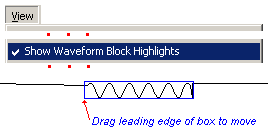
•A sine wave inserted between two high segments will look like this. |
|
Editing a Waveform Equation Block
•Checking the View > Show Waveform Block Highlights menu will draw blue boxes around all of the Waveform Equation Blocks. •Double clicking inside the blue box will open the Waveform Equation Block Properties dialog so you can edit the equation. |
|
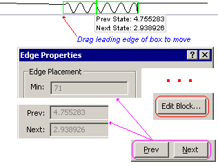
•If the blue boxes are not displayed, then double clicking will open the Edge Properties dialog. From here you can press the Edit Block button to open the Waveform Equation Block Properties dialog. •Equation Blocks cannot be edited from the Edge Properties dialog, but you can use the Previous and Next buttons to investigate events generated by the waveform equation block. •The first edge of a blue or green box can be dragged and dropped to move the entire block. |
|
Programming Waveform Equation Blocks
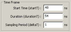
•Start Time sets where the block begins. The first event generated by the block will be at StartTime + Sampling Period. •Duration is the length of the block. The duration will always be truncated to be an integral number of sampling periods, so the last event in the block will be at Start Time + Duration (e.g. the end of the block). •Sampling Period is the time delta between events in the block. The smaller the sampling period, the more points that are generated for the block. |
|
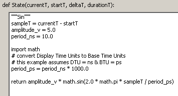
•State is the name of a Python function call that is evaluated for each event in the block to generate the extended state for that event. You define the body of this function to control what the block looks like. The parameters can be referenced in the function's body. |
currentT is the current time for the event (e.g currentT will be startT + deltaT for the first event and startT + durationT for the last event in the block). startT is the start time for the block. deltaT is the sampling period for the block. durationT is the duration of the block. |
•You can type in any Python code or edit the code of the default analog functions. •import math reads in the standard Python library code. •Most of the default functions have the statement sampleT = currentT-startT, which means that the analog block will have the same waveform shape regardless of the starting time of the block. To use absolute times instead of relative times for state calculations, just change this line to read: sampleT = currentT |
|
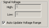
•The values in the Signal Voltage section are taken from the Analog Properties of the signal as described in Section 8.1: Analog Waveform Display. •Auto Update Voltage Range scans the entire signal and sets the maximum and minimum voltage values. This is equivalent to pressing the Get Min and Get Max buttons in the Analog Properties dialog. |
|
![]()
•Checking this control automatically sets the Analog Display box of the parent signal and sets the signal radix to Real so you do not have to manually set it. This only happens if the State function is written to generate 'real' values (State functions can also be used to generate digital patterns, in which case this check box has no effect). |
Advanced Waveform Equation Programming
Waveform Equation Blocks can access additional information about the timing diagram through our BtimPython module. While a Waveform Equation Block's code is executing, it can access the information about the waveform block through the global object currentWaveformBlock. From this object, you can navigate to objects representing the signal containing the block, the btim document, and other signals and event data in the document. This allows equations to generates state values based on either the event values of other signals or previous event values in the same signal.
There are several examples of equations which use the BtimPython API in the example file called waveform_block_equations.btim. The signals named from_text_file, product, and ramp_max_to_min demonstrate using the API to access the document's filename, get events from other signals, and access properties of the containing signal.
The full BtimPython API is documented in the file btim.html located in the SynaptiCAD/help directory. The BtimPython module is designed for use in stand-alone python programs as well as Waveform Equation Blocks. While all of the API functions can be called from a waveform equation block, many of the functions available in the module (such as creating new timing diagrams) will not be useful in this context.
Basing an Equation on the Preceding State Before the Waveform Block
It is often useful to define a waveform block equation so that it's waveform is a function of the state of the signal just before the waveform block begins. Two Python functions are available to get this preceding value, depending on whether the waveform block is generating analog (real values) or digital values:
•GetPrecedingRealValue() returns the state of the preceding event as a real value suitable for analog equations. •GetPrecedingState() returns the state of the preceding event as a string value (generally this will be a binary string) suitable for digital equations. |
The signals called uses_preceding_event and uses_preceding_digital in the waveform_block_equations.btim file contain waveform block equations that demonstrate usage of these two functions.
Formatting the Equation's Return Value for Digital Signals
When using Waveform Equation Blocks to generate analog equations, the python code fragment should return a python floating point value. Waveform Equation Blocks can also be used to generate digital signals. For digital signals, your Python code should return values as a strings of binary digits so that the signal's radix can post-process the value. For example, if you wish to return the hexadecimal value 'h71, you would want your python code to say: "return '1110001'". When the values are displayed to the user, they will be converted using the radix set in the Signal Properties dialog. For example, if the signal's radix is set to "hex" and the MSB:LSB is set to 15:0, that string will be formatted as 0071.
Two different ways of converting your digital values to binary strings are demonstrated in the signalsrandom and repeating_sequence in waveform_block_equations.btim. In the signal repeating_sequence, a decimal value is converted to a binary string using this python command:
valueAsBinary = '{0:b}'.format(value)