(TD) 1.10 Add the Setup for the Dinput to Clock |

|

|
|
(TD) 1.10 Add the Setup for the Dinput to Clock |
|
|
(TD) 1.10 Add the Setup for the Dinput to Clock |
|
|
|
(TD) 1.10 Add the Setup for the Dinput to Clock |
|
|
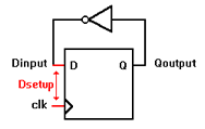
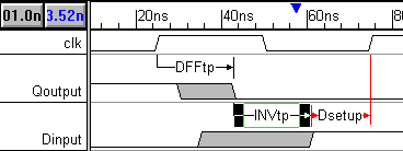
One of the most important features of a timing diagram editor is that setup and hold parameters can monitor pairs of signals transitions to make sure that they do not violate the timing constraints of the circuit. In this design, if Dinput changes too close to a clock edge then there is a risk that the flip-flop will go into a meta-stable state. We will use a setup parameter to make sure the Dinput does not violate the setup time for the clock. |
|
Add a Setup parameter:
•Press the Setup button so that right clicks will add setups. |
|
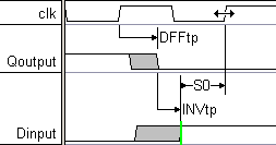
•Left click on one of the rising edges of the Dinput signal to select it. •Right click on the second rising edge of the clock to add a blank setup between the selected edge and this one. •Notice that the arrows of the setup are pointing to the control signal. This means that you added the setup correctly. |
|
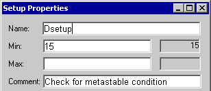
•Double-click on the new setup to open the Parameter Properties dialog and enter the following values: Name is Dsetup, min time is 15, and the comment is Check for metastable condition. •Press the OK button to close the dialog. |
|
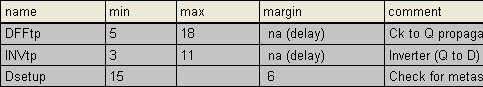
Notice that the margin column in the Parameter window says that there is a 6ns safety region before the setup is violated. Verify this by clicking on the maximum edge of the Dinput signal (to place the blue delta mark on the time line), then placing the cursor on top of the second rising edge of the clock. The blue time readout should say 21ns (measured time 21ns - setup time 15ns = 6ns margin).
Cause the Setup to be violated:
Next, we will demonstrate what happens when a setup is violated by increasing the inverter's delay.
•Double-click on INVtp to open the Parameter Properties dialog and change the max time to 18 ns. Then press the Apply button to apply the change. |
•Notice that the setup has turned red in the Diagram window and that the Margin value of the Parameter window has also turned red. •Change the inverter delay back to 11ns and click OK to close the dialog. |