(TD) 4.5 Drawing a Step Signal |

|

|
|
(TD) 4.5 Drawing a Step Signal |
|
|
(TD) 4.5 Drawing a Step Signal |
|
|
|
(TD) 4.5 Drawing a Step Signal |
|
|
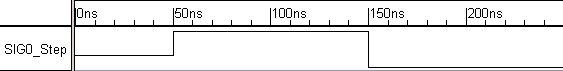
The analog signal from the previous step can now be easily converted to a step signal by adjusting the edge times for the segment that displays the change in value (The second and the fourth segments in our example). You can either use the mouse to move one of the edges of the segment to the same time as the other or you can use the Edge Properties dialog to adjust the edge times.
To use the Edge Properties dialog:
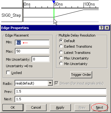
•Copy and Paste SIG0_Analog by selecting the signal name and using the Ctrl-C and Ctrl-V keys. Double click on the new signal to open the Signal Properties dialog and name the new signal SIG0_Step. |
•Double-click the first edge to open the edge properties dialog. •Make note of the Min time (50ns). •Click the Next button to move to the next edge (at 100ns). •Enter the Min time from the previous edge (50ns) in either the Min or Max edit box. Click Next to move to the next edge and apply the changes. •Notice that there is a vertical step at 50ns. •Move the edge at 200ns to 150ns using the same technique. |
|