(TD) 2.7 Design a Multi-Bit Counter |

|

|
|
(TD) 2.7 Design a Multi-Bit Counter |
|
|
(TD) 2.7 Design a Multi-Bit Counter |
|
|
|
(TD) 2.7 Design a Multi-Bit Counter |
|
|
When a muti-bit signal is clocked the register/latch circuit shown will be instantiated one time for each bit of the signal. This allows you to use one signal to represent the operation of a multi-bit counter or buffer.
Use a multi-bit signal to make counter:
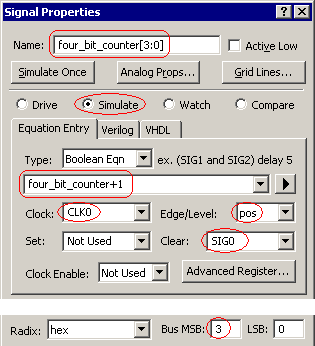
•Press the Add Signal button to add a new signal. •Rename the signal to four_bit_counter. •Set the type to simulate. •Type in the equation four_bit_counter +1. •Set the clock to CLK0 with an trigger edge of pos. This will make the signal change only on the positive edges of the clock. •Set the clear line to SIG0. If you press the Advanced Register button you can verify that the clear line with be active low and asynchronous, so that a pulse low on this line will clear the signal registers to zero. •Set the Msb to 3 to instantiate the multiple registers. |
|
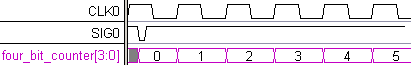
•Press the Apply button to simulate the signal. Notice that the signal will be a grey unknown region until the SIG0 goes low to clear the register. |
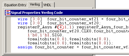
•If you press the Verilog tab, in the Signal Properties dialog you can see that the register is going to be 4 bits wide (it is the first parameter that is passed into the register). |