(TD) 2.2 Simulate a Boolean Equation |

|

|
|
(TD) 2.2 Simulate a Boolean Equation |
|
|
(TD) 2.2 Simulate a Boolean Equation |
|
|
|
(TD) 2.2 Simulate a Boolean Equation |
|
|
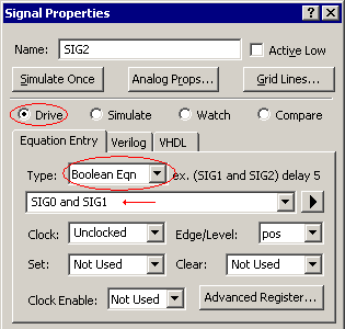
A simulated signal is created by adding a Boolean equation to the Signal Properties dialog for that signal. The dialog accepts Boolean equations in either VHDL, Verilog, or SynaptiCAD's enhanced equation syntax. The SynaptiCAD format supports the following operators: and or &, or or |, nand, nor, xor or ^, not or ~ or !, and delay. We will cover the delay operator in the next section.
Simulate a Boolean equation once:
•Double click on the SIG2 signal name to open the Signal Properties dialog. Move the dialog so that you can see the dialog and the 3 signals at the same time. •Enter SIG0 and SIG1 into the edit box below the Boolean Eqn type box (signal names are case sensitive). •By default, all signals are Drive signals that will only simulate when the user presses the Simulate Once button. |
|
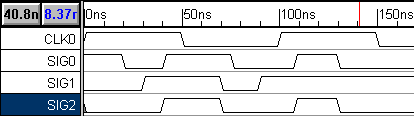
•Click the Simulate Once button at the top of the dialog and watch the signal draw itself. Notice that SIG2 is the result of the Boolean Equation "SIG0 and SIG1". SIG2 is drawn in black to indicate that it will not re-simulate automatically. |
Continuously Simulate the Boolean Equation:
•First make sure the program is in the continuously simulate mode: •If you are using WaveFormer, then check the Options > Diagram Simulation Preferences menu to make sure that the Continuously Simulate box is checked. WaveFormer does not have the Auto Run/Debug Run button. •If you are using VeriLogger Pro or TestBencher Pro, make sure that the program is in Auto Run simulation mode. Debug Run mode will not continuously update signals. The Auto Run/ Debug Run simulation mode button is located on the simulation toolbar, in the upper left of the window below the Project menu. |
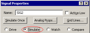
•To make the signal continuously simulate, check the Simulate signal type button. |
|
•Notice that the SIG2 is now drawn in purple. This color means that the signal is being continuously simulated, and changes in the input waveforms cause automatic re-simulations. |
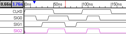
•Move some of the edges on SIG0 and SIG1 and watch SIG2 re-simulate. (Notice that you cannot drag and drop SIG2's signal edges because they are calculated edges). |