Timing Diagram Editor 2: Simulated Signals |

|

|
|
Timing Diagram Editor 2: Simulated Signals |
|
|
Timing Diagram Editor 2: Simulated Signals |
|
|
|
Timing Diagram Editor 2: Simulated Signals |
|
|
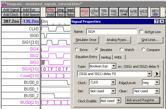
Simulated Signals reduce the amount of time needed to draw and update a timing diagram, because the waveform is described using a Boolean or registered logic equation. With Simulated Signals you will no longer have to figure the output of a combinational circuit or calculate the critical path of a synchronous circuit by hand. WaveFormer Pro has an internal interactive simulator that supports multi-bit equations with true min-max timing, unlike traditional simulators that can only represent single-valued delays. This tutorial contains some simple examples of Boolean and registered logic equations that showcase the simulator's capabilities.
To do this tutorial, you will need WaveFormer Pro or a higher level product. SynaptiCAD has also included Simulated Signals with the VeriLogger and TestBencher products, even though they have a built-in Verilog simulator, because this feature makes it easier to generate test benches and timing diagrams. In WaveFormer, it is the backbone of the timing analysis and design features.
This tutorial assumes that you are able to draw signals and can add delays, setups, and holds to those signals. We recommend that beginners start with the Basic Drawing and Timing Analysis Tutorial to learn the basics of timing diagram editing before attempting this tutorial.