(TD) 6.11 Modeling Tri-State Gates |

|

|
|
(TD) 6.11 Modeling Tri-State Gates |
|
|
(TD) 6.11 Modeling Tri-State Gates |
|
|
|
(TD) 6.11 Modeling Tri-State Gates |
|
|
There are 2 possible drivers for DBUS: the SRAMS which we modeled in section 9, and the tri-stated output of the DBUS_INC signal. All the drivers for a bus should be included in the code for the bus.
To add the tri-state gate to DBUS:
1. Double click on the DBUS signal name to open the Signal Properties dialog box.
2. In the direct HDL code edit box add a 4th line of HDL code to DBUS:
assign DBUS = WRITE ? DBUS_INC : 'hz;
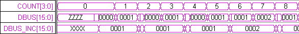
Line 4 models the tri-state gates that follow the latches in the histogram circuit. These tri-state gates are enabled whenever the WRITE signal is high. We use the conditional operator (condition ? x : y) which acts like an if-then-else statement (if condition then x else y). If WRITE is high, DBUS is driven by DBUS_INC (the incremented version of DBUS that we latched), else the tri-state drivers are disabled (‘hz means all bits are tri-stated).