(TD) 3.3 Repeat Parameters Across the Diagram |

|

|
|
(TD) 3.3 Repeat Parameters Across the Diagram |
|
|
(TD) 3.3 Repeat Parameters Across the Diagram |
|
|
|
(TD) 3.3 Repeat Parameters Across the Diagram |
|
|
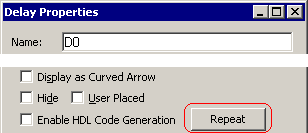
Once you have drawn a delay, setup, or hold parameter, that parameter can be automatically drawn between similar edges across the timing diagram. When the Repeat button, in the Parameter Properties dialog, is pushed the program will search for the next beginning edge, and add a parameter between that edge and the next ending edge. This will continue until the end of the diagram. Some caution should be taken when repeating delays because the delays cause edges to move.
Repeat D0 across the timing diagram:
•For this demonstration arrange Diagram window so that you can see the entire diagram. You may need to use the zoom-in buttons. |
•In the diagram window, double-click on D0 to open the Parameter Properties dialog. •Press the Repeat button. This will cause delays to be added to each of the falling edges of SIG0 that have a matching edge on SIG1. |
|
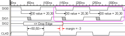
•Also notice that the margin for setup S0 is now violated and is displayed in red. This happened because the second D0 moved the edge on SIG1 that S0 is attached to. •Close the Parameter Properties dialog. |