(SDC) 8: VCD Simulation Files Generate SDC |

|

|
|
(SDC) 8: VCD Simulation Files Generate SDC |
|
|
(SDC) 8: VCD Simulation Files Generate SDC |
|
|
|
(SDC) 8: VCD Simulation Files Generate SDC |
|
|
SDC constraints can be derived directly from the timing information contained in simulation or logic analyzer waveforms. The process is similar to the previous steps, loading a waveform file and adding delays, setups, and holds. The difference is that since the timing of the simulated or captured waveforms is exactly the timing for the circuit, you can skip the step of entering values for the parameters by choosing to use "distance variables" rather than "value variables".
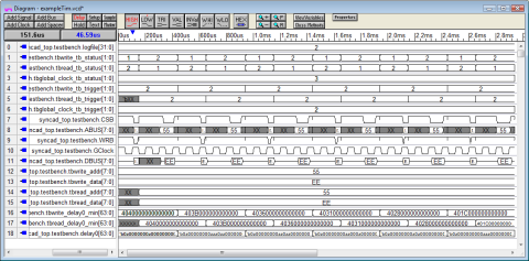
Load in a VCD waveform file generated by a Simulator:
•Choose the Import/Export > Import Timing Diagram From menu to open the Open File dialog. •Open the exampleTim.vcd file located in the C:\SynaptiCAD\Examples directory. |
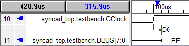
Add a Delay and enable the SDC Distance Variables:
•Zoom into the diagram, and add a delay between the GClock rising edge and the start of the DBUS cycle. |
|
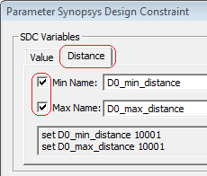
•Double click on the Delay to open the Delay Properties dialog. •Press the SDC Code button to open the Parameter Synopsys Design Constraint dialog. |
•Press the Distance tab. •Check the Min Name and Max Name check boxes to create the distance variables. These will take the actual value of the distance between the edges (i.e. timing values set by simulation or captured by logic analyzer). |
|
•In the SDC Commands section, check the Use Min/Max Distance Variables to use the variables you just created. •Also you will need to choose the SDC Command Type to generate. |
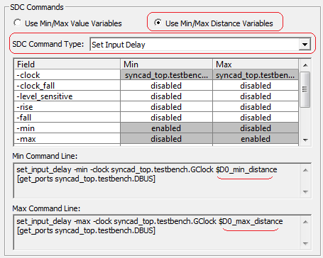
•Notice that the code at the bottom of the dialog is using the distance variables. |