(TBench) 2.4 Draw Stimulus Waveforms and Export Test Bench |

|

|
|
(TBench) 2.4 Draw Stimulus Waveforms and Export Test Bench |
|
|
(TBench) 2.4 Draw Stimulus Waveforms and Export Test Bench |
|
|
|
(TBench) 2.4 Draw Stimulus Waveforms and Export Test Bench |
|
|
First we will draw a write transaction, and export it as a simple stimulus based testbench. This transaction ignores the TRDY signal (an input to the testbench) and doesn't verify that the data was actually written successfully to the MUT. We will add that functionality in the next step.
Draw or Load the write cycle timing diagram:
•Quickly sketch the waveforms into diagram that we have been working with. If you have trouble drawing the waveforms, please review the Basic Drawing and Timing Analysis Tutorial before continuing with the rest of this tutorial. |
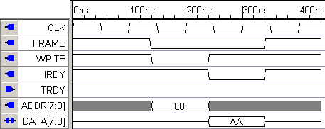
•Or load the completed write cycle timing diagram draw_single_write.btim located in the SynaptiCAD\Examples\TutorialFiles\ReactiveTestBench\Completed Diagrams directory. |
Export a Verilog or VHDL test bench:
As you proceed through this tutorial, you will periodically generate the test bench to see how the generated code changes as the timing diagram is edited.
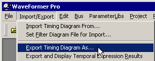
•Choose the Export > Export Timing Diagram As menu option to open the Export dialog. |
|
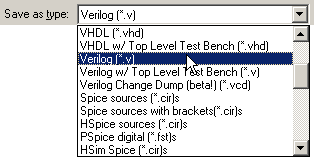
•In the Save as Type list box in the lower left corner of the dialog, choose either the Verilog or Verilog w/ Top Level Test Bench. The Verilog script just generates the test bench code. The Top Level Test Bench also includes an instantiation of the model under test. |
|
•Choose draw_single_write.v as the file name and click the Save button to close the dialog and generated a test bench called draw_single_write.v. •The file draw_single_write.v is automatically displayed in the Report window. If you cannot see the Report window, select the Window > Report Window menu option to bring the window to the top. |
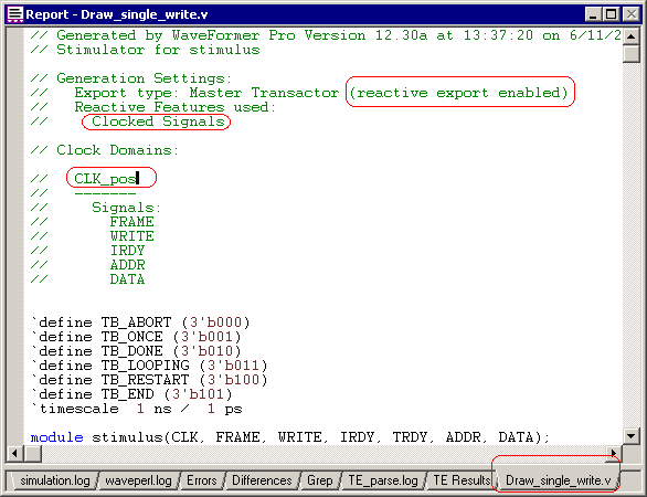
•View the generated code in the Report window. Notice that the comment at the top of the file shows that Reactive Export is enabled (if this is missing contact SynaptiCAD and get a license for this feature). •Also notice that code also shows that all of the signals are in the CLK_pos clock domain. We set this in the previous section when we set the clocking signal and edge. •Scroll through the code and quickly compare the code to the drawn waveforms. |