(TBench) 1.3 Export a Verilog Test Bench |

|

|
|
(TBench) 1.3 Export a Verilog Test Bench |
|
|
(TBench) 1.3 Export a Verilog Test Bench |
|
|
|
(TBench) 1.3 Export a Verilog Test Bench |
|
|
Test benches can be generated by both the File > Save Timing Diagram As and the Export > Export Timing Diagram As menus. However the File menu always defaults to the SynaptiCAD BTIM format. Once you setup the Export menu to the settings for your favorite export format, it will default to that format. If you are a VHDL-only person you can skip this and go to the next section.
Generate the Verilog Test Bench:
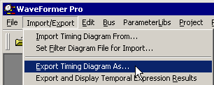
•Choose the Export > Export Timing Diagram As menu option to open the Export dialog. |
|
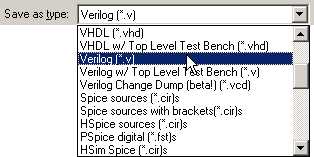
•In the Save as Type list box in the lower left corner of the dialog, choose the Verilog (*.v) script. This indicates that the timing diagram will be exported to a Verilog code file with a default file extension of ".v". |
|
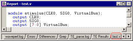
•Choose test.v as the file name and click the Save button to close the dialog. WaveFormer Pro will produce a Verilog file named test.v. •The file test.v is automatically displayed in the Report window. If you cannot see the Report window, select the Window > Report Window menu option to bring the window to the top. |
Compare the Code to the Diagram:
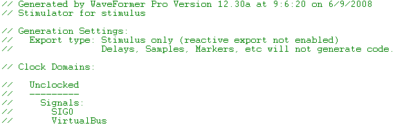
•At the top of the file there is a large comment section that describes how the code was generated, what the clocking domains are, and what program features were used to generated the code. In the basic testbench generation, all signals are in the Unclocked domain (all signals are delayed by time values). With the reactive test bench option, you can delay signals based on the occurrence of clock edges as well. |
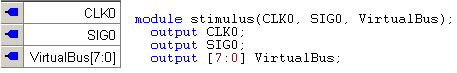
•Notice that each of the output signals in the diagram are also outputs of the generated stimulus module. These signals will hook up to your model under test. |
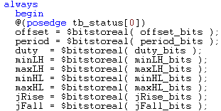
•CLK0 is defined as a clock signal in the timing diagram. The program generates a loop to represent the clock (rather than a series of assignment statements for each edge). Also notice that all of the clock properties such as buffer delay and rise and fall jitter will generate proper code. |
|
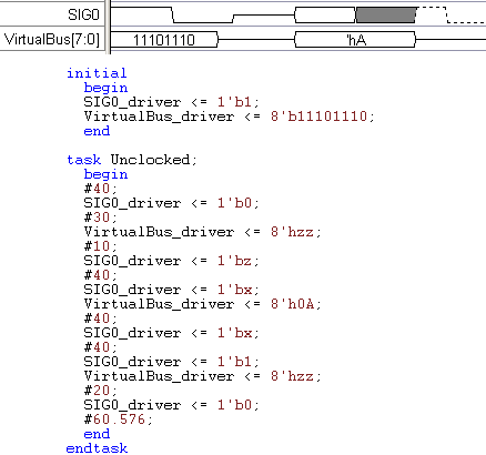
•Compare the signal waveforms to the generated code. Notice that the undefined valid state on SIG0 generates to 1'bx, but the defined valid states on Virtual bus generate out to the proper values. |