(TD) 6.3 Modeling State Machines |

|

|
|
(TD) 6.3 Modeling State Machines |
|
|
(TD) 6.3 Modeling State Machines |
|
|
|
(TD) 6.3 Modeling State Machines |
|
|
We will use a simple one-hot state machine to control the circuit, and we will model it using Boolean Equations. A one-hot state machine uses a single flip-flop for each state. At any given time, only the flip-flop representing the current state will contain a 1, the other flip-flops will be at 0 (hence the name one-hot).
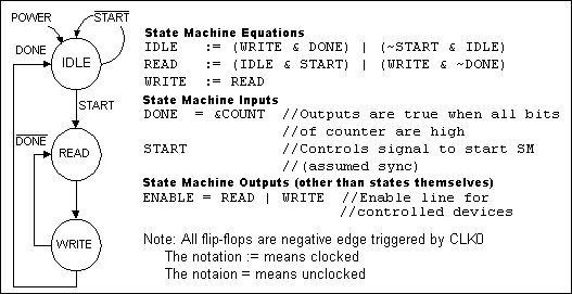
Figure 2: State diagram and design equations for the histogram controller state machine
The state machine (SM) initializes to the IDLE state. On the negative edge of the clock after START goes high, the SM will enter the READ state and look up the current count for the current address value being output by the A/D converter. This value will be incremented by a simple fast-increment circuit. On the next clock, the SM will enter the WRITE state, latching the incremented value into a transparent latch called DBUS_INC and initiating the write back of the incremented data to the SRAM. The state machine will continue to toggle between the READ and WRITE state until the desired number of data values have been histogrammed (determined by the size of the binary counter called COUNT), at which point the SM will return to the IDLE state. Figure 2 shows the SM that we will model.
The state machine is modeled in WaveFormer using one signal for each state. Next we will enter the equations for the state machine, however these signals are not simulated until Section 5 because signal DONE has not yet been defined.
1. Add 3 signals and name them IDLE, READ and WRITE.
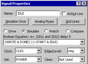
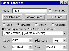
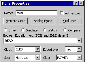
2. For each signal, enter state machine Equation, select Simulate button, setup the clock and trigger edge, and setup the set and clear signals as shown in the following pictures:
|
|
Notice the display ![]() in the bottom right hand corner and notice that the state machine signal names turned gray . This is because the IDLE and READ equations reference a signal called DONE. This signal has not been defined so if you try to simulate you get errors. In the next section we will investigate the different ways to detect and fix simulation errors.
in the bottom right hand corner and notice that the state machine signal names turned gray . This is because the IDLE and READ equations reference a signal called DONE. This signal has not been defined so if you try to simulate you get errors. In the next section we will investigate the different ways to detect and fix simulation errors.