(Sim) 1.5 Prepare for Graphical Test Bench Generation |

|

|
|
(Sim) 1.5 Prepare for Graphical Test Bench Generation |
|
|
(Sim) 1.5 Prepare for Graphical Test Bench Generation |
|
|
|
(Sim) 1.5 Prepare for Graphical Test Bench Generation |
|
|
So far in the tutorial, we have created a project and simulated some code using a manually written testbench, which is the traditional design flow using a simulator. In the next few sections, you will be drawing a testbench using SynaptiCAD's graphical testbench generator. Before we start, we must prepare the project by removing the manually written testbench file and clearing out the Stimulus and Results diagram. Then extract the MUT ports into the Stimulus and Results diagram.
Remove the Test Bench Source Code file and empty the Stimulus and Results Diagram:
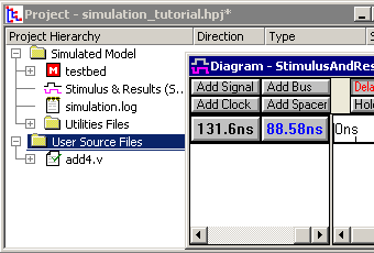
•Select the file add4test.v file in the project window and press the <delete> key. •Delete all of the signals in the Stimulus and Results diagram by selecting the signal names and pressing the <delete> key. •Verify that only add4.v is listed on the project tree, and that the diagram is empty. |
|
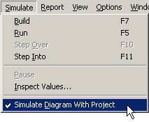
Verify that BugHunter is in the proper mode to generate a test bench:
•Verify that the Simulate > Simulate Diagram With Project menu option is checked. This option lets the simulator compile both the drawn waveforms and the Verilog source code files together. If this is unchecked, then no testbench will be created. |
|
Extract Ports from the Model Under Test (MUT):
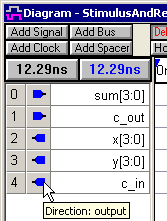
In the previous section, the Stimulus and Results diagram displayed only signals output by the simulator (the results). This diagram can also hold a testbench that will exercise the model under test (the stimulus). First we will extract the ports from the model under test and later we will draw the test bench.
•Press the Extract the MUT ports into Diagram on the simulator button bar. |
|
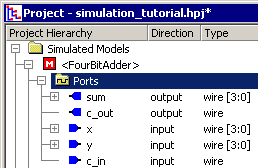
•Notice that the Stimulus and Results diagram is populated with the ports of the FourBitAdder module (see project tree below). These will be the signals that you will draw on in the next section. •The blue icons pointing to the right are inputs to the test bench (outputs of the model under test). The icons pointing to the left are outputs of the test bench (stimulus that drives the model under test). The tool-tip will always show you the direction if you forget. |
|
•The Extract the MUT function makes a guess as to which model is the model under test and displays that model with single brackets, <>, underneath the Simulated Model folder. It guessed correctly for this tutorial. |
|
•If you wanted to pick a different model under test, right click on a different model under the User Source Files list and pick Set as Model Under Test (don't do this for this tutorial). |