(TD) 2.5 Set and Clear Lines |

|

|
|
(TD) 2.5 Set and Clear Lines |
|
|
(TD) 2.5 Set and Clear Lines |
|
|
|
(TD) 2.5 Set and Clear Lines |
|
|
The Set and Clear lines are useful when defining circuits whose initial value needs to be specified. In this example we demonstrate how to design a divide by 2 circuit using a negative edge triggered register with an asynchronous active-low set line.
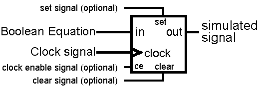
Use the Set line to define an initial state:
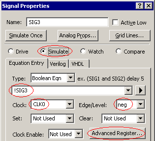
•Click the Add Signal button to create a new signal named SIG3. Then double click on the signal name to open the Signal Properties dialog. •Check the Simulate button. •Type !SIG3 into the Boolean Equation edit box (it references itself ). •Choose CLK0 from the Clock drop down list box. •Choose neg from the Edge/Level box. |
|
•Notice that the waveform for SIG3 is completely gray but that the status bar (in the lower right corner of the window) reports Simulation Good. This is because SIG3's Boolean equation references itself but it does not provide the simulator with a known start state. |
|
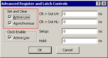
•Press the Advanced Register button to open the Advanced Register and Latch Controls dialog. Notice that the register and latch propagation, setup, and hold times, clock enable, and set/clear options are set here. Tip: the Global defaults are set using the Options > Simulation Preferences menu. |
|
•Make sure the Active Low and the Asynchronous check boxes in the Set and Clear section are checked. Click OK to close the dialog. |
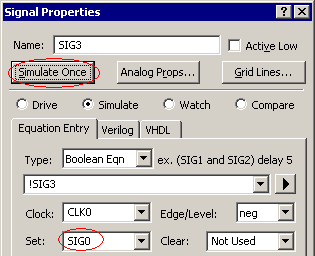
•Choose SIG0 from the Set drop down list box. •If you hid SIG0 in a previous section, choose the View > Show and Hide Signals menu to show SIG0. •Press the Simulate Once button to notify the simulator of the change in the model. |
|
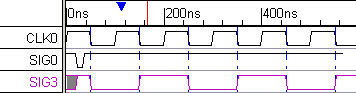
•Notice that SIG3 now has a simulated waveform. Redraw SIG0 so that it goes low early in the timing diagram, and then stays high for four or five clock cycles. |
|
•Experiment with SIG0 to see how the active low set line affects the operation of the flip-flop. Remember that we set the model to have an asynchronous low set signal. •To make the above diagram, we hid the unused signals. We also changed the clock grid so that the starting event was 2 and there were 2 events per line, that way we got grid lines on just the negative edges. |