3.2 Group Buses |

|

|
|
3.2 Group Buses |
|
|
3.2 Group Buses |
|
|
|
3.2 Group Buses |
|
|
Group buses are composite signals whose transitions and state values are determined by their member signals. Group buses are usually created from single bit signals that have been imported from logic analyzers or VCD files so that the aggregate value of the bus can be easily viewed. A group bus can either be edited directly by changing the bus value or indirectly by editing a member signal. Member signals can be hidden or displayed as needed. During most exporting operations (e.g. to VHDL or Verilog), only the member signals will be exported. The group bus will not be exported since it only duplicates the information in the member signals.
This section covers group buses that are used primarily for digital buses, but they can also be used to create differential signals for both analog and digital signals. Differential signals are covered in Section 3.4: Differential signals.
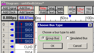
Create a Group Bus from existing signals (Most Common):
•Select the signal names in order from lowest bit to highest bit of the bus. •Click on the Add Bus button on the left-hand side of the button bar this will open the Choose Bus Type dialog. •Choose the Group Bus |
|
Create a Group Bus and it's member signals:
•Make sure that no signals are selected (clear selected signals by clicking in the Diagram window), then click the Add Bus button to open the Add Bus dialog. •Type the name of the bus into the Name box. The member signals will be named the same name as the bus plus their bit index (e.g. BUS0_0, BUS0_1, etc.). If you would prefer the member signals be named as BUS0[0], BUS0[1], etc, first create a virtual bus and convert it to a group bus. •Select the Group Bus radio button, then type in the MSB and LSB to set the size of the bus |
Editing Techniques for Group Bus:
If you are doing a lot of drawing, consider converting to a Virtual Bus which is a lot faster to work with than group buses.
•Draw waveforms on either the Bus signal or on the member signals. •Double click on a Bus segment to open the Edit Bus State dialog and type in either a Binary or Hex field value. (Virtual state is not used for group buses, because the member signals have to have defined single bit values). •The Hex box accepts numerals 0-F. The Binary box accepts numerals 0 and 1. Both boxes also accept L, H, Z, V, and X, where L = weak low, H = weak high, Z = tristate, V = valid, and X = invalid state. •Clear Red Events: Editing group buses with the Hex button often cause lots of small red rectangles or spikes to appear on the member signals. These mark and preserve the edges on the member signals that now have same state on both sides of the edge. To remove the red marks and merge all adjacent same-state segments, select the Edit > Clear Red Events menu. |
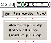
When you manually draw on the member signals of a group bus, slight differences in the edge times of the member signals will cause multiple edges to be created on the group bus. The Align and Bind features can be used to clean up the edges of the group bus.
•Click on the bus edge to select it, so that the Bus > Align, Bind, and Unbind menus are activated, then choose one of the menus to perform the action. •Align to Group Bus Edge will move all the of the nearby member signal transitions (within 10 pixels) to the exact time of the selected bus edge. Make sure to align the edges before adding a delay to a group bus edge, so that all the member signals will also be bound by the delay. |
|
•Bind Group Bus Edge will group together all the member signal transitions at the selected bus edge time, so that whenever a transition is moved (on any member signal), all the bound transitions will also move. •Unbind Group Bus Edge menu will ungroup the binded edges so that if a member signal's transition moves, the rest of the transitions at the same time do not move. •Delete a Group Bus by selecting its name and pressing the Delete key or by choosing the Bus > Expand & Delete Bus menu. Deleting a bus will also delete any parameters attached directly to the bus. The menu method also shows any member signals which might have been hidden. |
Display Techniques for Group Buses:
•Display Hex or Binary data by double clicking on the group bus name to open the Signal Properties dialog and choosing either Hex or Binary from the Radix box. •Hide Member Signals by selecting their names and choosing View > Hide Signals. •To hide member signals automatically during the creation of the bus, choose the Options > Drawing Preferences menu option to open a dialog, and check Hide signals on bus merge control. |
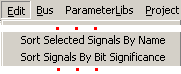
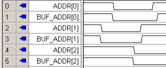
•If you need to visually compare the member signals on two different group buses, you can use the Edit > Sort Signals by Bit Significance menu to reorder the signals. •Note in this example that the individual bits of two group busses are interleaved. |
|
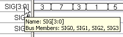
•Display the member signals of a Group Bus in a tooltip by using the mouse to hover over the bus name. |
|