(TD) 2.10 Simulated Bus Signals |

|

|
|
(TD) 2.10 Simulated Bus Signals |
|
|
(TD) 2.10 Simulated Bus Signals |
|
|
|
(TD) 2.10 Simulated Bus Signals |
|
|
Simulated Buses are similar to Group Buses. The primary difference is that the bus is generated using a Boolean Equation. A simulated bus can be referenced in another signal's Boolean equation, (group buses cannot). Also, TestBencher will generate a Boolean equation for the timing transaction so that the simulated bus can include input signals as member signals.
Create a Simulated Bus:
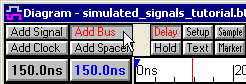
•Make sure that no signals are selected, and press the Add Bus button to open the Add Bus dialog. Note, if a signal was selected a different dialog will open and you cannot add a simulated bus from there. |
|
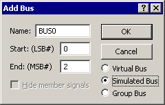
•Set the LSB to 0 and the MSB to 2. •Select the Simulated Bus radio button. •Press the OK button to close the dialog and create the bus and member signals. |
|
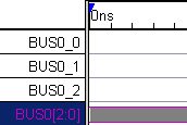
•BUS0''s waveform will be grey because none of the member signals are defined. |
|
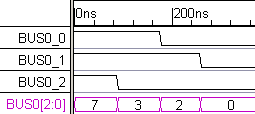
•Draw on the member signals and see the bus simulate. |
|
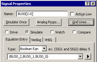
•Double click on BUS0[2:0] label to open the Signal Properties dialog. Notice that the bus is defined as a concatenation of the member signals. |
|