(Sim) 2.6 Compare simulation results against expected results |

|

|
|
(Sim) 2.6 Compare simulation results against expected results |
|
|
(Sim) 2.6 Compare simulation results against expected results |
|
|
|
(Sim) 2.6 Compare simulation results against expected results |
|
|
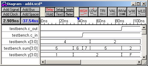
In this step we will compare the simulation results against the expected waveforms that we drew in an earlier section. The compare feature is an option that can be added on to WaveFormer Pro.
A) Load the Simulation Results file into WaveFormer Pro
•Select the Import/Export > Import Timing Diagram From menu option and load the add4.vcd file created in the previous step to open the Import Waveforms dialog. |
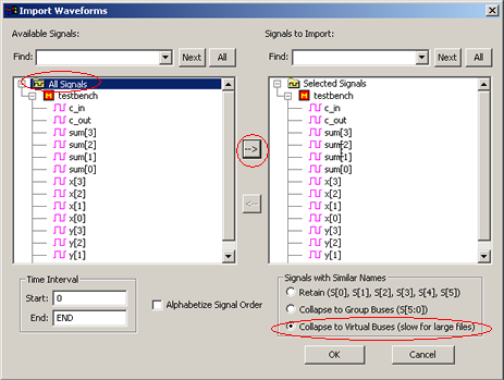
•Check the Collapse to Virtual Buses box, so that the signals will be imported as buses instead of as individual bits. •In the left hand pane, select the All signals node then press the => button to move the signals to the right hand pane. Then press OK to import the diagram. |
B) Strip out the Simulation Model Names
Before we can compare the VCD file to the expected results btim file, we must make sure that the signal names are the same. During simulation, the model name "testbench." prefix was added to each of the VCD’s signals. We can either strip out the name from the simulation file or add the prefix to the expected waveforms. Either way, we can use the Search and Rename Signals dialog to strip or add a prefix. Here we will strip the prefix from the simulation vcd file.
•Select the Edit > Search and Rename Signals menu to open the Search and Rename Signals dialog. |
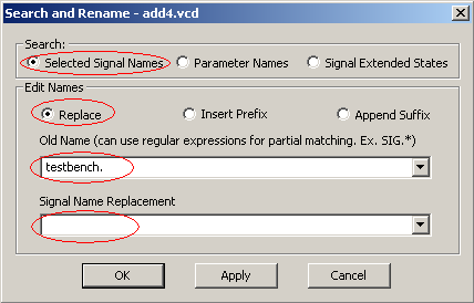
•Check Selected Signal Names to make the dialog operate on the signals. Since we did not have any signals selected in the diagram, this will operate on all the signals by default. •Check Replace to make the dialog do a replace. If we had decided to add "testbench." to the names in the timing diagram, we would have to use insert prefix to add the prefix. •Set the Old Name pattern to "testbench." making sure that you include the period after testbench. •Leave Signal Name Replacement blank, because we just want to strip out the name. •Press OK to strip the prefix from the signal names. |
|
C) Compare The Timing Diagrams
To do this step, you will need to have a license for the Compare Feature. This is normally turned on in the evaluation version, but must be purchased in the full version.
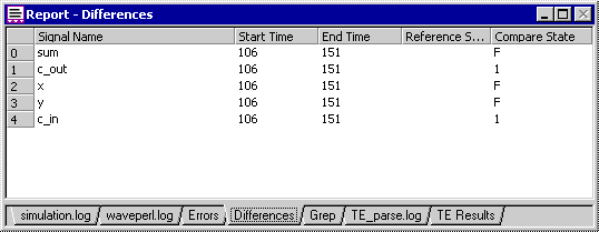
•Choose the File > Compare Timing Diagram menu to open a file dialog and select the file add4test.btim that you created earlier in the tutorial. •The differences between the VCD file and the expected results file will show up in red. The differences are also displayed in list form in the Differences tab in the Report window. |
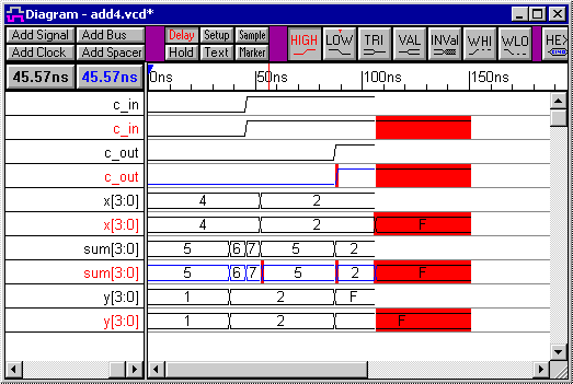
•When drawing the btim file waveforms, you may have some differences with the diagram shown on the tutorial. These differences will show up as highlighted lines in red in the comparison diagram. Minor differences can be removed by using the compare tolerances. |
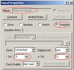
•Click the SET ALL button on the compare toolbar to open the Signal Properties dialog |
|
•Notice that the Name box is greyed out. This means that the dialog is operating on all the compare signals. •Type in a tolerance of 5 for both the the –Tol and +Tol controls. This will allow the compare feature to ignore small changes in values. •Click the OK button to apply the changes |
|
•Press the Compare All Compare Signals button to re-compare the waveform signals. |
|
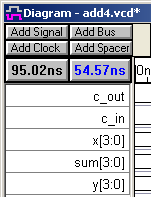
•Below is the resulting diagram. Notice that the thinner lines in red have now disappeared. The remaining differences occur at the end of the waveforms because the simulator stops the simulation as soon as there are no more changes on the waveforms. |
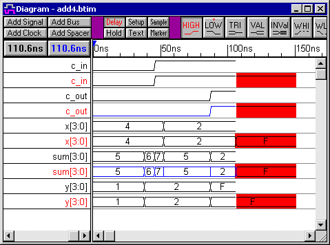
•Also look at the Differences tab in Report window, which shows a hyperlinked list of the differences. If you cannot see the Report window, then choose the Window > Report menu option to bring it to the front. |