(TBench) 3.6 Create the Read Cycle Transaction Diagram |

|

|
|
(TBench) 3.6 Create the Read Cycle Transaction Diagram |
|
|
(TBench) 3.6 Create the Read Cycle Transaction Diagram |
|
|
|
(TBench) 3.6 Create the Read Cycle Transaction Diagram |
|
|
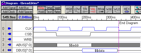
The read cycle will initiate a read transaction with the clocked SRAM and also monitor the data bus to verify the result of the read. Since the signals for the read diagram are so similar to the write diagram, we will start by copying the write diagram and then modify the waveforms (instead of starting with the template).
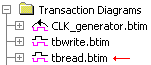
Copy the tbwrite diagram to make tbread:
•Click on the tbwrite diagram window bar so that it is the active window, then choose File > Save Timing Diagram As menu to open the Save As dialog •Name the file tbread, and press the Save button. |
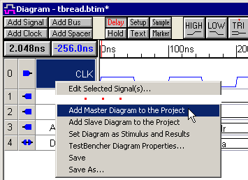
•Right-click in tbread's Label window, and select Add Master Diagram to Project from the context menu. This will add tbread to the Transaction Diagrams folder in the Project window.
|
|
Modify the WRB Signal:
The write control signal, WRB, should stay high (inactive) for the duration of the read.
•Select the center segment and press the delete key to remove the low signal segment. |
|
Modify the DBUS Signal:
Since our SRAM is clocked the data comes out on the clock cycle after the chip select signal, CSB, goes active. You can drag each edge of DBUS individually, or use the following technique to shift the whole signal.
•Shift the start of the DBUS data segment to 200ns. Hold down the <2> key (the number 2 key) on the keyboard, while dragging the starting transition to 200ns. The <2> key causes transitions to the right of the selected edge to move with the dragged edge. |
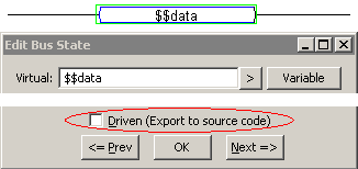
During the read transaction, the DBUS signal will be driven by the SRAM so it will be an input signal to the test bench (not an output like in the write cycle).
•Double click on the data segment to open the Edit Bus State dialog. •Uncheck Driven (Export to source code) checkbox.This will cause the segment to be displayed in blue. |
|
•Click the diskette icon |
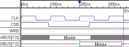
The completed read diagram looks like the following: