(TD) 1.6 Editing Signal Waveforms |

|

|
|
(TD) 1.6 Editing Signal Waveforms |
|
|
(TD) 1.6 Editing Signal Waveforms |
|
|
|
(TD) 1.6 Editing Signal Waveforms |
|
|
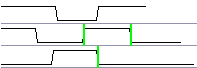
This section covers the main editing techniques used to modify existing signals (Note: these techniques will not work on clocks, because they draw themselves). The most commonly used technique is the dragging of signal transitions to adjust their location. Most of the other techniques all act on signal segments, the waveforms between any two consecutive signal transitions. The segment waveform can be changed, deleted, or a new segment can be inserted within another segment. Use each of the following techniques:
1) Drag-and-Drop Signal Transitions:
•Left click and hold down the mouse button on a signal transition and drag it to the desired location. |
|
•To move transitions on different signals simultaneously, first select multiple transitions by holding the <CTRL> while clicking on edges. Then drag a transition to desired location. |
|
2) Click-and-Drag to insert a segment into a waveform or select to delete:
•Inside of a segment, click and drag the cursor to insert a segment |
|
•The inserted state is determined by the red state button |
|
•Delete a segment: Select a segment (see above) and then press the delete key on the keyboard. |
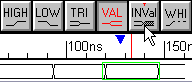
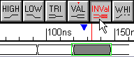
3) Change a segment's graphical state by selecting it and then pressing a state button:
•Click in the middle of the segment to select it (so that it has a green box around it). |
|
•Click on a state button to apply that graphical state to the segment. If you change a segment to the same state as an adjacent section, the transition will turn red to preserve the edge data. This transition can be deleted if necessary. |
|
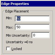
4) Find the exact edge time and see how to lock an edge
•Double-click on an edge of the signal transition to open the Edge Properties dialog. •To move an edge, enter a new min or max time. An edge only has one time until uncertainty is added either by using a delay parameter or the min uncertainty box in this dialog. •To lock an edge so that it cannot be moved, check the Locked checkbox. If a delay ends on a locked edge it will turn red if it cannot force the edge to the proper time. |
|
•Note: All edges on a signal can be locked by selecting the signal name, and then choosing the Edit > (Un)Lock Edges of Selected Signals from the main menu. •Make sure to unlock any signals or edges you locked in this tutorial, or else your delay in the next section may not be able to force its ending edge. |
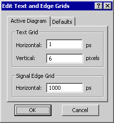
5) Adjusting the drawing Grid
Drawn signal transitions are automatically aligned to the closest grid time. The grid does not affect the placement of edges that are moved by delays or formulas. By default the grid is set to the display time unit, because this generates nice VHDL and Verilog stimulus generation files with whole number times (like 2ns instead of 2.465ns). However, it is sometimes convenient to set the grid to a multiple of the clock frequency to make all new signal edges line up with the clock edges.
•Select the Options > Grid Settings menu item to open the Edit Text and Edge Grids dialog. •You do not have to make any changes to this dialog. Just notice that you are able to control the Signal Edge Grid. •Also notice that text objects have a different grid. |
|
6) Adding virtual state Information to a segment
•For Signals, double-click on the middle of a segment to open the Edit Bus State dialog, and then type in a new value into the Virtual edit box. |
|
•For Clocks, press the Hex button and then double-click on the middle of the segment to open the Edit Bust State dialog. If the Hex button is not pressed, the double-click will open a different dialog to allow editing of the clock. |