(TD) 6.6 Modeling Combinational Logic |

|

|
|
(TD) 6.6 Modeling Combinational Logic |
|
|
(TD) 6.6 Modeling Combinational Logic |
|
|
|
(TD) 6.6 Modeling Combinational Logic |
|
|
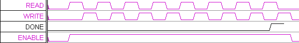
In addition to the state signals, the state machine has one other output signal called ENABLE that is used to enable the SRAM, the DONE counter, and the ADC. ENABLE is just the output of an OR gate with the READ and WRITE signals as inputs. In Section 3 we used the Boolean Equation interface to model the flip-flops of the state machine. We will use the same interface to model combinatorial logic. To do this choose the default clock called unclocked. If a signal other then unclocked is selected, then the Boolean Equation interface models registers or latches depending on the type of Edge/Level trigger selected. Chapter 12 covers the advanced features of the Boolean Equation interface including the min/max delay features.
Model the Enable logic:
1. Create a new signal called ENABLE.
2. Enter the equation: READ | WRITE into the Boolean Equation edit box in the Signal Properties dialog.
3. Check the Simulate radio button.
4. Verify that ENABLE is the OR of READ and WRITE. If ENABLE did not simulate, use the techniques found in section 4 to find your error. Remember that signal names are case-sensitive.
5. Click OK to close the dialog.