(SDC) 5: Signal Direction |

|

|
|
(SDC) 5: Signal Direction |
|
|
(SDC) 5: Signal Direction |
|
|
|
(SDC) 5: Signal Direction |
|
|
Signal Direction does not directly affect SDC code generation. However, it does affect testbench generation and it adds a bit of readability to the diagram because the little blue icons before the signal name indicate direction. This can be helpful as a visual check in the next steps, because when creating SDC constraints you will generally be adding delays to inputs of your design and setup/holds to the outputs of your design.
By default, all signals and clocks have a direction of output (an output from the timing diagram, in this case from the FPGA's perspective). So if you are drawing the timing diagram, you would might want to change some of the signals to inputs and bidirectional signals by changing the Direction box in the Signals Properties dialog. There is a quick way to select multiple signals and change the directions at the same time, which we will now demonstrate with the clocks.
Example of multiple editing:
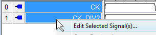
•Select both clock signals by pressing the <Ctrl> key while left clicking on the clock names. •Then RIGHT click and choose Edit Selected Signals from the context menu. |
|
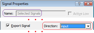
•Notice that the Name box in the Signal Properties dialog is greyed and says Selected Signals. This indicates that multiple signals are being edited. •Choose Input from the Direction drop-down near the bottom of the dialog. •Close the dialog. |
|
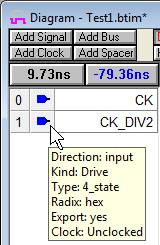
•If you hover over the icon to the left of the clock name you can see that the signal is now set to Input. Also the little blue icons are pointing in a different direction. |
|