(SDC) 4: Sketching the Waveforms |

|

|
|
(SDC) 4: Sketching the Waveforms |
|
|
(SDC) 4: Sketching the Waveforms |
|
|
|
(SDC) 4: Sketching the Waveforms |
|
|
At this point in the tutorial you can either continue to add the signals and parameters as described or you can open a partially completed timing diagram and make changes to enable SDC code generation.
TIME SAVER: Load Histogram_sdc.btim:
•Choose File > Open Timing Diagram and open histogram_sdc.btim located in the SynaptiCAD > Examples > TutorialFiles > SdcTutorial directory. •For Project Users: In the timing diagram, right click in the signal name pane and choose Add Diagram to the Project from the context menu to add the diagram to the project. •For Non-Project Users: Choose Report > Open Report Tab and pick the file with the SDC file extension that has the same name as your timing diagram (e.g. histogram_sdc.sdc or test1.sdc). |
Sketch the Waveforms:
Next Sketch the waveforms for the ADC and Synchronous SRAM control signals.
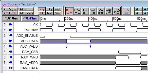
•Add the above signals and sketch the waveforms. The first Timing Diagram Editor: Basic Drawing Tutorial gives detailed instructions on the drawing environment. For review: •The Add Signal button adds signals. •Double clicking on a signal name opens a dialog where you can change the name and set the direction. •Left clicking to the right of the last waveform will draw a waveform section of the type that is selected on the waveform buttons. The waveform buttons toggle between the red one and the one with the little red T above the name. •Move signal edges by dragging and dropping them. •Change a waveform segment by selecting it then left clicking on a new waveform type. |