(SDC) 2: Enter Master Clocks |

|

|
|
(SDC) 2: Enter Master Clocks |
|
|
(SDC) 2: Enter Master Clocks |
|
|
|
(SDC) 2: Enter Master Clocks |
|
|
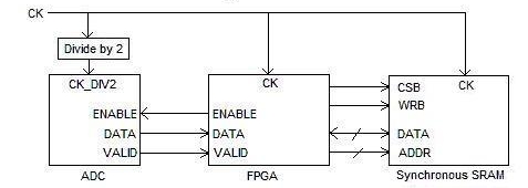
Generally it is a good idea to start an SDC timing diagram by creating the clock signals, since most of the timing will be related to the clocks. In this design example, we have a master clock and a derived clock that is a "divide by 2" of the master clock. Each clock will need to enable SDC code generation.
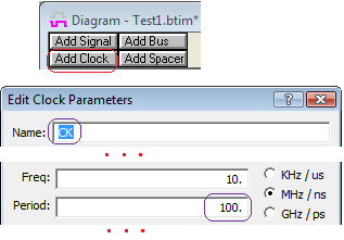
Create the Master Clock:
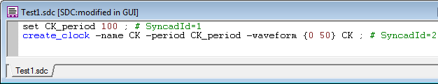
•Press the Add Clock button to create a clock and open the Edit Clock Parameters dialog. •Name the clock CK. •Set the period to be 100ns. •Clocks do not generate SDC code until you enable the SDC generation. To do this, press the SDC Code button at the bottom of the dialog to open the Clock Synopsys Design Constraint dialog. |
|
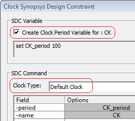
•Check the Create Clock Period Variable check box to automatically create an SDC variable called CK_period. •From the Clock Type drop-down choose Default Clock. This controls the type of SDC clock command that is generated. A default clock is a clock that attaches to an actual input pin of your design. •Close the two dialogs. |
|
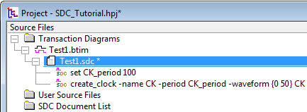
Looking at the Code In the Report Window:
The Code can be viewed and edited in the Report Window. For Project Users just double click on the line in the Project window. For non-project users, open the file separately in the report window.
•In the Project window, notice that you can see the SDC code generated under the timing diagram node. •Double click on the code to open the code in a Report window. |
|
•For non-project users, save the timing diagram, then choose Report > Open Report Tab and pick the file with the SDC extension that has the same name as your timing diagram. |
•The SDC code can be directly edited in the Report window and the timing diagram will change to match the code. |