(TD) 1.14 Drawing Group Buses and Differential Signals |

|

|
|
(TD) 1.14 Drawing Group Buses and Differential Signals |
|
|
(TD) 1.14 Drawing Group Buses and Differential Signals |
|
|
|
(TD) 1.14 Drawing Group Buses and Differential Signals |
|
|
Group Buses display the aggregate value of their member signals. Normally, you would use them after importing from a format that treated all signals like one-bit signals (like from a logic analyzer). They are also used to create differential signals, which are just two bit group buses with some special display settings. Before a group bus can be created, its member signals must either be specified by selecting the signal names or new signals need to be created. We will use both methods in this tutorial.
To create a group bus and its member signals:
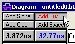
•Make sure that no signal names are selected (clear selected signals by clicking in the Diagram window), then press the Add Bus button to open the Add Bus dialog. If signals are selected, they will become the member signals of the bus (we will do that next). |
|
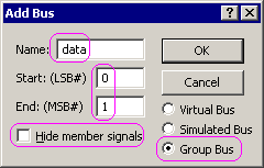
•Name the bus data and set the LSB to 0 and the MSB to 1. •Check the Group Bus button. •Verify that the Hide member signals check box is NOT checked. We want to be able to see the member signals in this demonstration. |
|
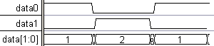
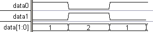
•Press the OK button to close the dialog and create the bus. There should be 3 signals generated: data (the bus), and data0 and data1 (the bus member signals). If the member signals are not shown, use the View > Show Hidden Signals to show them. |
•Draw High and Low segments on data0 then draw the opposite on data1 (later we will use these to make a differential signal). |
|
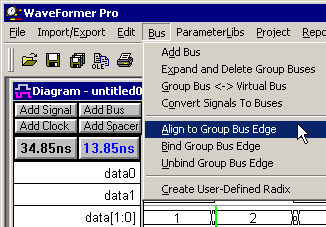
•Notice that the edges in the data bus are a little ragged because the edges of the member signals are not on exactly the same times. •Select an edge on data and choose the Bus > Align to Group bus edge to snap all the edges together. All the edges can be locked together by using the Bind menu. |
|
•Note the bus edge can be locked to the member edges at a particular time by selecting and edge and choosing the Bind Group Bus Edge menu as shown above. |
|
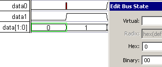
•Note that you can edit the data bus values by double clicking on a segment to open the Edit Bus State dialog and changing the Hex or Binary state (but not the virtual state). The member signals change to reflect the new value. |
|
•The red event on data0 preserves the edge on the member signal, so that you can make consecutive changes in the bus values without stopping to add edges. To remove the red events choose the Edit > Clear Red Events menu, but don't to it now. Just return the first state to 1. |
Creating a group bus from existing signals:
Here we will create a bus using existing signals by selecting the signal names in order from LSB to MSB, then adding the bus. We will make a bus with the opposite order from the last bus.
•Select data1 by clicking on the name. This will be the LSB of the new bus. •Select data0 by clicking on the name. This will be the MSB of the new bus. |
|
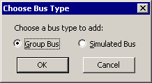
•Press the Add Bus button to open the Choose Bus Type dialog. Notice that the New Bus dialog did not open up because this bus will be automatically created from the selected signals. |
|
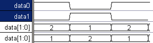
•Select the Group Bus radio button and click OK to close the dialog. Notice that a new bus, data, was added to the diagram and that it has a different MSB and LSB than data. |
Create a Differential Signal
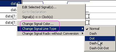
•Differential signals look best when the line type and color of one of the member signals is different. Right click on the data0 signal and use the menus to change the signal color to blue and the signal line type to dot. |
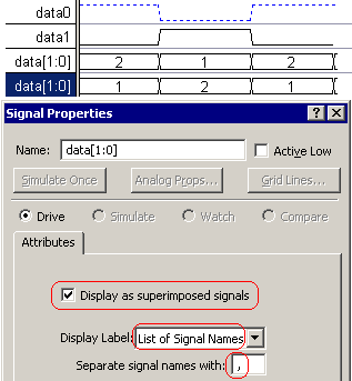
•Double click on the second data bus to open the Signal Properties dialog. •Check the Display as Superimposed signals so that the signals will draw on top of each other, instead of the normal state value display. •Change Display Label drop-down to List of Signal Names so that the bus name is replaced with the list. |
|
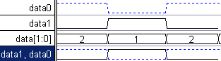
•Press the Ok button to close the dialog and display the bus as a differential signal. |
|