(TBench) 3.4 Setup the Template Diagram |

|

|
|
(TBench) 3.4 Setup the Template Diagram |
|
|
(TBench) 3.4 Setup the Template Diagram |
|
|
|
(TBench) 3.4 Setup the Template Diagram |
|
|
When TestBencher created the project it also generated a template diagram. New transaction diagrams that are created for this project will contain the same signals, waveforms, parameters, and properties as the template diagram. Currently the CLK signal is the only signal in the template diagram. You are going to add the port signals for the clocked SRAM to the template so that later when you create the timing diagrams for the project all of the signal information matches up.
Extract the ports from the SRAM into the template diagram:
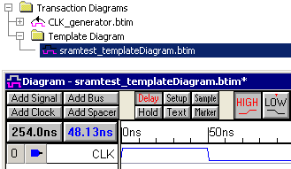
•In the Project window, under the Template Diagram folder, double click on sramtest_templateDiagram.btim to open the template diagram window. |
|
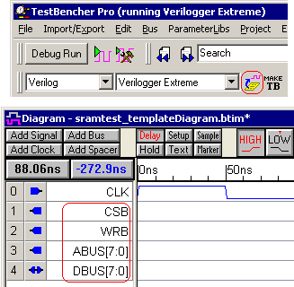
•Click the Extract Ports from MUT •The blue icons indicate the direction of the signals. DBUS has a direction of inout, because the data bus will need to both drive data to the SRAM model and receive data back from it. The CLK is an input to the diagram because it is driven by the CLK_generator diagram (the blue waveform also indicates it is an input). The rest are outputs of the test bench which will drive stimulus to the SRAM model under test. |
|
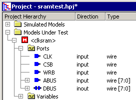
•Notice that <clksram> is now present in the Project window under the Models Under Test folder. The single angle brackets indicate that clksram is the Model Under Test. Expanding this tree will display signal, port, and component information of the MUT. |
|
Note: If <clksram> was not generated as the MUT, then change the simulation preferences by choosing the Options > Diagram Simulation Preferences menu. Check the Auto-create test bench and tree check box. Press the Extract Ports from MUT button to rebuild the MUT.
Add an end diagram marker:
The transaction diagrams use an End Diagram Marker to indicate the exact time that the transaction ends. You can add an end diagram marker to the template diagram, so all new transactions will get the marker.
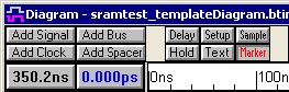
•Press the Marker button so that right clicks will add Marker lines to the diagram. |
|
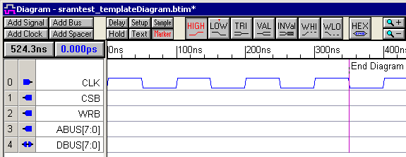
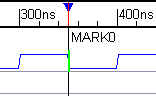
•Click on the fourth falling edge of the CLK signal (at 350ns) to select it and turn it green. Then right-click to add the marker line. |
|
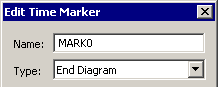
•Double-click on the marker to open the Edit Time Marker dialog. •Select a Marker Type of End Diagram from the drop down list box. This end diagram marker will force the transaction to end at the fourth falling edge of the CLK signal. |
|
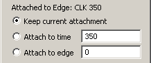
•Notice that the Marker is Attached to Edge on CLK at 350ns. This is because you selected the edge before adding the marker. These controls can be used to changed the attachment. |
|
•Select Type from the Display Label list box. This will cause the marker to display its type rather then its name. |
|
•Click OK to close the Edit Time Marker dialog. •Use the File > Save All Files menu option to save the project and the template diagram. |
The completed template diagram should look like the following: