1.4 Colors, Line Type, Size, and More Visual Controls |

|

|
|
1.4 Colors, Line Type, Size, and More Visual Controls |
|
|
1.4 Colors, Line Type, Size, and More Visual Controls |
|
|
|
1.4 Colors, Line Type, Size, and More Visual Controls |
|
|
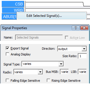
There are many ways to control how signals and waveforms are displayed including color, font, line thickness, edge slant, and signal spacing. These settings are found by double clicking on a Signal name to open the Signal Properties dialog, or by right clicking on the signal to open the context menu.
Editing More than One Signal at a time
•Most of the display features are available for editing by groups of signals. Just select a set of signals by pressing the <CTRL> button while left clicking on the names, then right click on one of the selected signals and choose Edit Selected Signals from the context menu. •To edit a single signal, just double click on the signal's name to open the dialog.
|
|
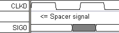
Insert Spacer Signals:
•Press the Add Spacer button to insert a horizontal space into the diagram below the selected signal. See the size feature below to adjust the height of a spacer signal. |
|
Grid Lines on Signals:
•Double click on a signal name to open the Signal Properties dialog, then press the Grid Lines button to open the Grid Options dialog (see Section 2.3 Grid Lines on Clocks and Signals). |
|
•The grid lines will still be visible if the controlling signal is hidden and the View > Show Hidden Text menu is checked. This lets you create patterns of grid lines without having the attached signal disturbing the circuit information. |
Individual Waveform Settings with right click menus and Signal Properties dialog:
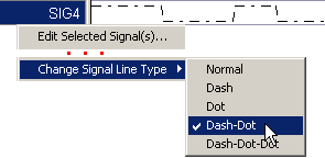
•Line type: right click on the signal name and choose Change Signal Line type to pick a different line type like Dashes or Dots. (Line thickness is a global controls shown below) |
|
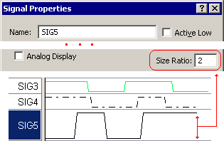
•Height of one Signal: double click on the signal name to open the Signal Properties dialog and set the Size Ratio to increase the height of the signal. •Height of all Signals: Select the Options > Drawing Preferences menu to open the Drawing Preferences dialog. The Waveform Height sets the height of all of the waveforms. |
|
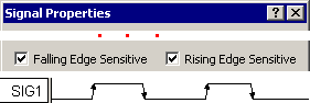
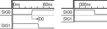
•Arrows on waveform edges: double click on the signal name to open the Signal Properties dialog and check the Falling Edge Sensitivity or Rising Edge Sensitivity boxes. These are also used by TestBencher Pro for sequence recognition. |
|
Global Signal Waveform Controls using the Drawing Preferences Dialog:
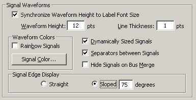
•Select the Options > Drawing Preferences menu to open the Drawing Preferences dialog and look at the Signal Waveforms section. •Synchronize Waveform Height to Label Font Size keeps the waveform height relative to the height of signal label font. |
|
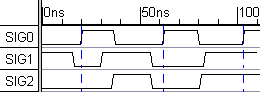
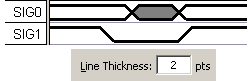
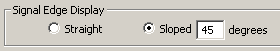
•Line Thickness can be increased and the edges can be made Straight or Slanted. In the picture, the signals have a thickness of 2 and a slant of 45% (default is 75%). •To make straight edges for just one signal, clock, or an Analog Signal, check the use straight edges in the Analog Properties dialog, see Section 8.1 Analog Waveform Display. |
|
•Dynamically Sized Signals, if checked, will allow the space between signals to automatically change height as parameters are scrolled off the screen. |
|
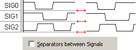
•Uncheck Separators Between Signals to remove the grey lines between signals. |
|
•Hide Signals on Bus Merge hides the member signals when a group bus is created, see Section 3.2: Group Bus. |
Global Controls that effect text inside signal waveforms using the Drawing Preferences Dialog:
•Select the Options > Drawing Preferences menu to open the Drawing Preferences dialog and look at the Text Inside Signal Waveforms section. |
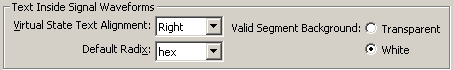
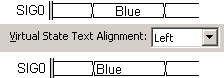
•Virtual State Text Alignment controls whether the virtual state text in a segment will appear centered, left-justified, or right-justified. |
|
•Default Radix specifies the base in which signal values are displayed for all new signals. Individual control is in the Signal Properties dialog. |
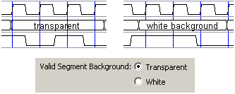
•In DataSheet Pro, the Valid Segment Background setting specifies whether the background color of a valid segment will over write other objects like markers and text objects. |
|
Color Controls for Waveforms and Signal Names
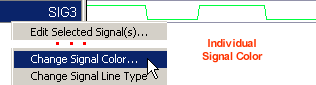
•Color One Waveform: right click on signal name and choose Change Signal Color. A global setting for all signals is shown below |
|
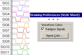
•Color All Waveforms: Choose Options > Drawing Preferences to open the dialog. •Rainbow Signals changes the signals to multi-colored waveforms. •Signal Color changes the color of all of the signals in the diagram (this only works if rainbow signals is unchecked). |
|
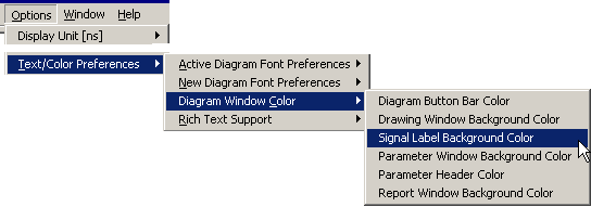
•Color of Label Window and Drawing Window: Choose the Options > Text/Color Preferences menu. There are several sub-menus that are used to set the different font and color properties. The Active menus change the current diagram. The New menus change the default settings for new diagrams. |
•Simulated signals by default are displayed using purple signal color, but they can be made to display using the normal signal color by unchecking the View > Show Default Simulated Signals color menu. |
Global Signal Name Controls using the Drawing Preferences Dialog:
•Select the Options > Drawing Preferences menu to open the Drawing Preferences dialog and look at the Signal Names section. |
|
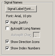
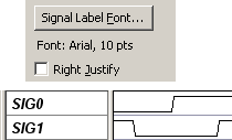
•Signal Label Font changes the font used for signal names. •Right Justify causes the signals names to be lined up on the right side of the label window. Un-checking it causes it to be left justified. |
|
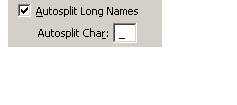
•Autosplit Long Names: allows the program to split signal names that are too long for the display. They will be split at the Autosplit Char. |
|
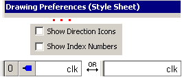
•Hide the index and direction columns in the signal label window by unchecking the Show Direction Icons and Show Index boxes. |
|
Width of the Label window:
•Drag-and-drop the bar separating signal names and signal waveforms. |
|
Change the default naming conventions of the Label window:
•Right-click on the Add Signal button to open the Modify Auto Name Prefix dialog. •Enter the new prefix so that each new signal will be named Prefix#, instead of the default Sig#. |