(TBench) 3.8 Create the Initialize Transaction Diagram |

|

|
|
(TBench) 3.8 Create the Initialize Transaction Diagram |
|
|
(TBench) 3.8 Create the Initialize Transaction Diagram |
|
|
|
(TBench) 3.8 Create the Initialize Transaction Diagram |
|
|
When drawing the waveforms for a transaction diagram it is important to remember that transactions do not automatically include an event at time zero and that only the drawn events are driven. This is a feature that allows transactions to be reused any time during simulation without implying any initialization information. In our example, the clocked SRAM control signals, CSB and WRB, need to be initialized before the read and write cycles are applied to the model. We will draw a simple initialization diagram that will drive the control signals to high (inactive).
Create the Initialization diagram from the Template diagram:
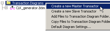
•In the Project window, right click the Transaction Diagrams folder and select Create a new Master Transactor from the context menu. This will cause the Save As dialog to open. |
|
•Name the file tbinitialize and press the Save button. This creates a new timing diagram using the information in the template file and lists the file in the Transaction Diagrams folder. |
|
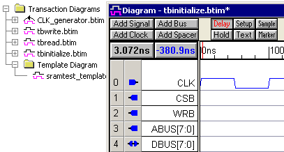
Edit the Waveforms:
•Remove the ABUS and DBUS signals, because the tri-state bus signals do not need to be initialized. Select the ABUS and DBUS signals by clicking on them, and then press the <delete> key to delete the selected signals. |
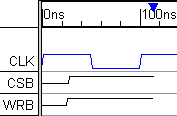
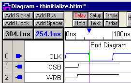
•Draw the following waveforms as shown (tristate for 10ns then high). If you need a help drawing, refer to the Basic Drawing and Timing Analysis Tutorial sections 1.5 Drawing Signal Waveforms. |
|
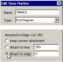
Move the End Diagram Marker:
The initialization timing diagram will only need one clock cycle to initialize the control signals. Therefore, the End Diagram marker can be moved to the 1st negative clock edge.
•Double-click on the marker to open the Edit Time Marker dialog. •Select Attach to Edge from the radio buttons. •Click OK to close the Edit Time Marker dialog. This will put TestBencher into a special select mode. |
|
•As you move the cursor around in the diagram a green bar will jump to the closest edge to remind you that you are in the Attach to edge mode. Click on the first negative clock edge (at 50ns) to attach the marker to that edge. |
|
•Click the diskette icon |