(TBench) 2.8 Drive Waveform Values using a File |

|

|
|
(TBench) 2.8 Drive Waveform Values using a File |
|
|
(TBench) 2.8 Drive Waveform Values using a File |
|
|
|
(TBench) 2.8 Drive Waveform Values using a File |
|
|
This step will use an ASCII input file to drive the DATA bus during the write cycle so that we can model a memory array. The basic idea is to create a user-defined array variable that is initialized from a file containing the values stored in the memory, then drive the DATA bus using the values of this array (using the current address value as the index for the array).
View the Input File:
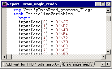
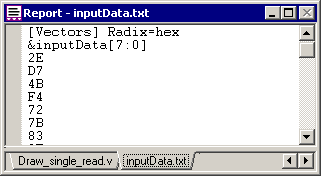
Waveform data values can be driven from a file that is in SynaptiCAD's spreadsheet format as defined in the Timing Diagram Editor Manual Section 11.11 Import from Spreadsheets. Basically the [Vectors] section is a tab separated format, where each column is a different variable. We have already created the file to save time, but you can view it.
•Choose the Report > Open Report Tab menu to open a file dialog. Set Files of Type to text (*.txt). •Browse to the SynaptiCAD\Examples\TutorialFiles\ReactiveTestBench\inputData directory and select inputData.txt then press the Open button to open the file in the report tab. |
Create a Variable and Link it to a file:
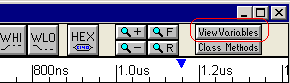
•Click the View Variables button in the diagram to open the Variable List dialog. |
|
•Press the New Variable button, then click on the name and change it to inputData. This name is important because it must match a column name in the input file that we choose. •Under the Structure column double click and select array. •Set Size to 256 to indicate that we are creating an array of 256 elements. •Set Data Type to 2_state then change MSB to 7 (this indicates we’re storing 8-bit values in the array). |
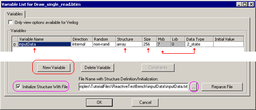
•Check the Initialize Structure With File checkbox near the bottom of the dialog. •Browse to the SynaptiCAD\Examples\TutorialFiles\ReactiveTestBench\inputData directory and select inputData.txt. •Press OK to close the dialog |
Make the diagram reference the variable:
In the previous step we created an array variable called inputData that hooks up to a file that has a column titled inputData. Here we will make the DATA signal use the array to supply the signal values for both the write and the read cycles. In the next two sections we will add a variable called address which will be used to move through the array and a loop so that multiple write-read cycles can be performed without having to draw the transaction over and over again.
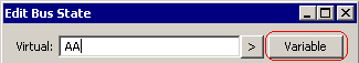
•Double-click on one of the AA states to open the Edit Bus State dialog then press the Variable button to open the Select Variable dialog. |
|
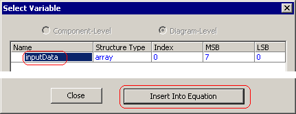
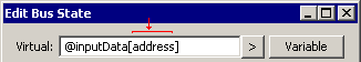
•Select the inputData variable, then press the Insert Into Equation button. This puts the variable into the Virtual box of the Edit Bus State dialog, so that you do not have to remember the exact syntax of the variable. |
|
•Edit the equation so that it says@inputData[address].The @ symbol is used to refer to a variable defined in the Variable List dialog. The address variable will be defined in the next section |
|
•Use the next or previous buttons to move to the other AA state and type in the same equation. |
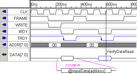
Below is a picture of the diagram. The variables do not show in the valid waveform at this zoom level because they are longer than the valid segments. If you zoom in you can see the variable names.
To see the generated code, export the test bench and view the code in the Report tab that contains the generated code. To see the code that initializes the inputData array, seach for "inputData". Next, look at the CLK_pos sequence, and search for "address" to find the assignment statement that drives the DATA bus with a value from inputData indexed by the address variable (the address variable will be created in the next step).