1.1 Adding Signals and Signal Properties |

|

|
|
1.1 Adding Signals and Signal Properties |
|
|
1.1 Adding Signals and Signal Properties |
|
|
|
1.1 Adding Signals and Signal Properties |
|
|
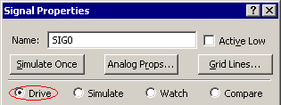
Signals can quickly be added using the the appropriate button below. Double clicking on the name of a signal opens the Signal Properties dialog which sets the properties for a specific signal including it's name, export type, display features and whether or not the waveform is generated by a Boolean equation. This dialog can also edit several signals simultaneously.
To add a new signal:
•Click the Add Signal button. |
|
•Note: The above buttons are located in a timing diagram window. You can open a new timing diagram window using the File > New Timing Diagram menu. |
Edit a signal's name and other properties:
•Double-click on a signal name to open the Signal Properties dialog and type in a new name. •Active Low signals are displayed with a bar (line) drawn over the top of the name. In equations, active low signals are referred to as name$BAR. |
|
•Drive is the default state used for drawn signals and is the most common signal state for signals in a timing diagram. The other states are used by special features: Simulate is for creating continuously simulated signals (see Section 4.1: Boolean Equations with Delays), Compare is for waveform comparison signals (see Section 9.1: Performing a Signal Compare), and Watch is used by the BugHunter environment for watching signals in a simulation (see Section 2.2: Watching Signal and Component Waveforms in the BugHunter manual for more information). |
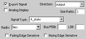
•Radix determines the base in which signal values are displayed. •Bus MSB and LSB determines the bit size of the signal. A single bit signal is (0,0). Chapter 3 covers buses and differential signals. |
|
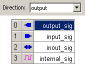
•Direction sets the port direction of the signal relative to the testbench. Output signals drive the model under test. Input signals represent signals with data coming back from the model under test. Internal signals are signals that are not connected to the ports of the model under test. The direction is also shown as an icon to the left of the signal name in the label window. To turn off this column choose the Options > Draw Preferences menu and uncheck the Show Direction Icons box. |
|
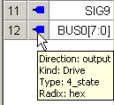
•A quick way to view a signal's properties is to put the mouse over the direction column and a tooltip will appear. Placing the mouse over the signal's name shows a tooltip of the full signal name, which is handy for signals with long names. |
|
Signal Name Rules: Normally spaces are not allowed in signal names. For documentation purposes, you can get spaces into a signal name by using the Edit > Search and Rename menu. However, adding spaces to signal names may cause problems when exporting to different formats or simulating Boolean Equations. Signal names beginning with "$$" are reserved for internal use. Signal names should not be the same as common Boolean operators (examples: AND, OR), if you plan to export to VHDL.
To move or sort signals:
•Section 1.11: Selecting, Moving, and Sorting Signals describes several techniques for moving signals with the mouse or sorting them into a particular order. The easiest way to move a signal is to select the signal label and drag it using the mouse. Also, the Edit > Sort Signals By Name menu will rearrange signals in alphabetical order. |
To delete a signal or multiple signals:
•Click on one or more signal names to highlight the names and then press the Delete key. When a signal is deleted, any parameters or text connected to it are also deleted. The Edit > Undo or Edit > Undo Delete menu item will undo a mistaken delete. |
Change the Auto Name generation:
•By default, signals are named SIG# but the "SIG" prefix can be changed by right clicking on the Add Signal button to open the Modify Auto Signal Name Prefix dialog and entering a new prefix. Bus and Clock prefix names work the same way. |