1.2 Drawing Waveforms |

|

|
|
1.2 Drawing Waveforms |
|
|
1.2 Drawing Waveforms |
|
|
|
1.2 Drawing Waveforms |
|
|
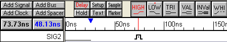
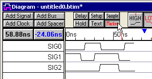
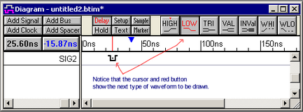
The timing diagram editor is always in drawing mode so left clicking on a signal will draw a waveform. The red state button controls the type of waveform that is drawn (high, low, tri-state, valid, invalid, weak high, and weak low). The buttons toggle back an forth between two states, and the next state is indicated by the little red T on top. Click on the state buttons to set the toggle and next state.
![]()
To draw the waveform of a signal:
•Place the mouse cursor inside the Diagram window at the same vertical row as the signal name.The red state button on the button bar determines the type of waveform drawn. The cursor shape also mirrors the red state button. |
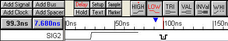
•Click the left mouse button. This draws a waveform from the end of the signal to the mouse cursor. |
|
•Move the mouse to the right and click again to draw another segment. |
|
•Keep drawing from left to right across the diagram. |
|
•Pressing the middle mouse button either toggles the state buttons or cycles through them depending on the setting in the General Preferences dialog. Choose Options > General Preferences menu to open the dialog. |
There are several mouse-based editing techniques used to modify existing waveforms. These techniques will only work on signals that are drawn. They will not work on generated signals like clocks and simulated (blue) signals that are covered in later chapters.
1) Drag-and-Drop a Signal Transitions:
•To move one transition, click on the transition and drag it to the desired location. |
|
•To move all of the transitions on one signal, hold down the <1> and <2> number keys while dragging. Holding down just the <1> key moves all the edges to the left, and the <2> key moves all the right. |
|
•To move transitions on different signals, first select the transitions by holding the <CTRL> while clicking on them. Then select and drag on the final selected edge to move all the selected transitions an equal distance in time. |
|
2) Click-and-Drag to insert a segment into a waveform:
•Inside of a segment, click and drag the cursor to insert a segment |
|
•The inserted state is determined by the red state button |
|
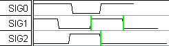
3) Change a segment's graphical state by selecting it and then pressing a state button:
•Click in the middle of the segment to select it (so that it has a green box around it). |
|
•Click on a state button to apply that graphical state to the segment. If you change a segment to same level as an adjacent section, the transition will turn red to preserve the edge data. This transition can be deleted if necessary. |
|
4) Adding virtual state Information to a segment
Chapter 3.1: Virtual Buses covers all of details of Virtual states on buses.
•For Signals, double-click on the middle of a segment to open the Edit Bus State dialog, and then type in a new value into the Virtual edit box. |
|
•For Clocks, press the Hex button and then double-click on the middle of the segment to open the Edit Bust State dialog. If the Hex button is not pressed, the double-click will open a different dialog to allow editing of the clock. |
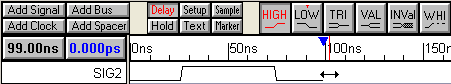
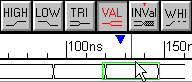
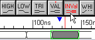
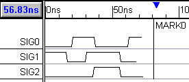
5) Making Waveforms end at a common time
•Sketch waveforms, then press the Marker button down. |
|
•Right click in the diagram window past the ends of the waveforms to add a time marker line. |
|
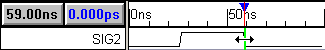
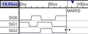
•Double-click on the time marker line to open the Edit Time Marker dialog, and check the Signal ends snap to marker control. |
|
•Note that the waveforms snap to the marker, but are not truncated. All signal transitions remain intact, even if the marker is moved. Only the last segment of the signal ends at the marker |
|
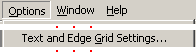
5) Adjusting the drawing Grid
Drawn signals transitions are automatically aligned to the closest grid time. The grid does not affect the placement of edges that are moved by delays or formulas. By default the grid is set to the base time unit, because this generates nice VHDL and Verilog stimulus generation files with whole number times (like 2ns instead of 2.465ns). Sometimes it is convenient to set the grid to a multiple of the clock frequency to make all new signal edges line up with the clock edges.
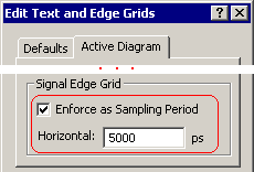
•Choose the Options > Text and Edge Grid Settings menu item to open the Edit Text and Edge Grids dialog. |
|
•The Signal Edge Grid section controls where the waveform edges will be placed on the Horizontial grid. •The Enforce as Sampling Period control is used by the Analog State Label equations and does not effect the drawing of signals (see Section 8.3: Sine, Capacitor, Ramp & Exponential waveforms). A newer method of generating analog waveforms that are editable as equations are described in Section 8.2: Waveform Equation Blocks for editable Analog waveforms. |
|
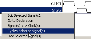
7) Snap signal transitions to the closest clock edge
A quick way to line up the edges of signal is to snap them to the previous clock edge using the Cyclize Selected Signal(s) context menu.
•Sketch a waveform that is close to lining up with a clock. |
|
•Setup the signal's clocking signal, by double clicking on the signal name to open the Signal Properties dialog, and set he clocking signal using the Clock box and set the Edge/Level to both (or just neg or pos if you only want to snap to those edges). |
|
•Right-click on the signal name and choose Cyclize Selected Signal(s) from the context menu. |
|
•Notice that the edges are lined up with the clock edges |
|
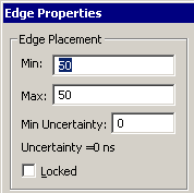
8) Finding the exact edge time and locking the edge
•Double-click on an edge of the signal transition to open the Edge Properties dialog. Section 1.5 discusses timing analysis features of this dialog. •To move an edge, enter a new min or max time. •To lock an edge so that it cannot be moved, check the Locked checkbox. |
|
•Note: All edges on a signal can be locked by selecting the signal name, and then choosing the Edit > (Un)Lock Edges of Selected Signals from the main menu. |
•The Prev and Next buttons moves the dialog to the previous or next edge on the signal. |
|