(TD) 3.10 Marker Loops and Pipelines |

|

|
|
(TD) 3.10 Marker Loops and Pipelines |
|
|
(TD) 3.10 Marker Loops and Pipelines |
|
|
|
(TD) 3.10 Marker Loops and Pipelines |
|
|
Loop and pipeline markers can be used to document sections of the timing diagram.TestBencher Pro uses these markers to generate code for test benches and the code generation features are covered in the TestBencher Pro Basic Tutorial. Since these are markers will generate code, the timing diagram editor requires that both the beginning and ending markers are either attached to time or attached to the same type of edge on the diagram.
Add a Pipeline Marker:
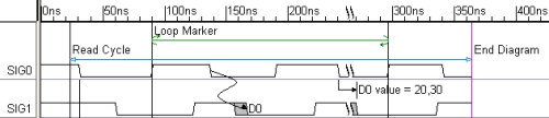
Pipelines begin with a pipeline boundary marker and end at either another pipeline boundary marker or an end diagram marker. Since we already have an end diagram marker we will only need to add a beginning marker to draw the pipe.
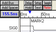
•In the last step we pressed the Marker button so that right clicks will add markers to the diagram. |
|
•Make sure that no edges are selected in the diagram, and then right click at the top of the diagram at about 25ns. This will add a marker to the right of all the drawn signals. |
|
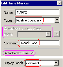
•Double click on the marker to open the Edit Time Marker dialog. Notice that the attachment is listed as Time because no edges were selected when the marker was added. •From the Marker Type box, choose Pipeline Boundary. If the program can match this with another boundary marker or end diagram marker it will draw a blue horizontal line between the two markers. •For most of the timing diagram editors, the Semaphore box is disabled. In TestBencher the Semaphore name would be centered above the pipe line marker. |
|
•In the Comment box enter some text like Read Cycle. •From the Display Label box, choose Comment to make the marker display its comment instead of its name. •Press OK to close the dialog. Notice that a blue pipeline marker has been drawn across the diagram. |
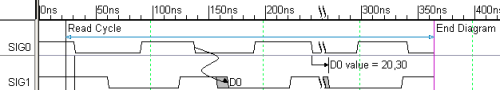
•The horizontal line can be moved by dragging and dropping the marker label to a new position. |
Investigate Loop Markers:
Loops begin with one of the Loop marker types (for loop, while loop, repeat loop) and end on an end loop marker. Both the begin and end loop markers must be either both be attached to time or both be attached to the same type of edge on a particular signal. Since these are so similar to pipelines we will not add one in this tutorial, but the following picture shows what the Loop looks like in the diagram. This is a For loop attached to the rising edges of SIG0.