SYNAPTICADcolon APPLICATION NOTES


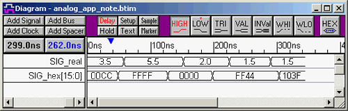
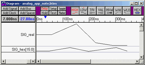
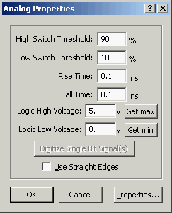
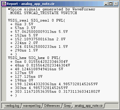
Creating Analog Signals and Exporting to SPICE

SynaptiCAD's entire line of timing diagram editors can create and display analog signals. Each signal has a complete set of analog properties that control how digital values are converted into analog values. If a signal has a radix of real, the values of the signal will be exported directly as voltage values. If a signal has a radix except real, an internal Digital to Analog converter will use the bus size and the logic voltage level settings to convert the digital waveform value into an analog value.


Creating analog signals:

  • Add some signals and waveforms. Drawing digital signals with HIGH and LOW waveforms will cause the exported signal to use the max and min voltages. To make it more interesting we have drawn the signals using VALID segments and used the HEX button to add values to the segments.

Timing Diagram image with digital waveform display.
  • Double clicking on the signal name opens the Signal Properties dialog, which allows the editing of the signal's radix and bus size. In the above picture, we have added a signal with a radix of real and one with a radix of hex to demonstrate the difference between exporting real voltage values and using the internal DAC to calculate the voltage value.

Signals Properties Dialog
  • The Analog Display check box causes the waveforms to be displayed as a magnitude plot. The Size Ratio edit box increases the height of the signal. In the image below we set SIG_real's size ratio to 4.

Timing Diagram image with analog waveform display.

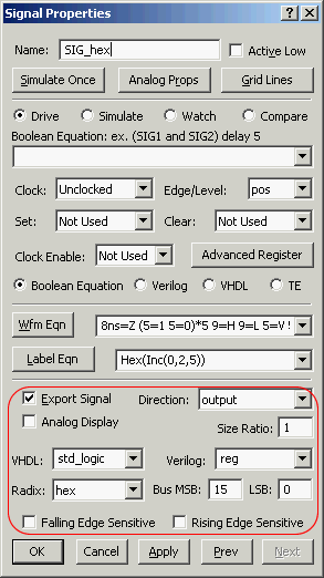
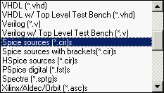
All of SynaptiCAD's timing diagram editors except for Timing Diagrammer Pro can export signals to SPICE and PSPICE formats.


To export analog signals:

  • First setup the analog properties of each signal. Double click on a signal name to open the Signal Properties dialog.

  • Press the Analog Props button to open the Analog Properties dialog

Analog Properties Dialog
  • The Get max and Get min buttons grab the min and max values from the signals waveform and use them to set the logic high and low voltage levels. These are particular useful for signals with a real radix. Other radixes use the bus size of the signal to determine where in the voltage range each value lies.

  • The High Switch Threshold and Low Switch Threshold allow you to determine a high and low detection limit. The percentages entered in these edit boxes determine the point at which the value will be read as the voltage high or voltage low value.

  • The Rise Time and Fall Time edit boxes can be used to specify the amount of time it takes for the signal to go from the High Switch Threshold to the Low Switch Threshold.

  • Next use the Export > Export Timing Diagram as menu to open a save dialog.

  • Choose one of the SPICE formats from the Save as Type drop down.

View of Export Format menu
  • After you save, the file will also be loaded in the Report window

Report Window with Spice Code

Back to Application Notes