|
|||||||||||||||||||||||||||||||||||||||||||||||||||||||||||||||||||||||||||||||||||||||||||||||||||||
|
|
Generate PI-2005 Stimulus VectorsWaveFormer Pro and TestBencher Pro generate stimulus files for Pulse Instruments PI-2005 Pattern Generator. Programming a pattern generator with enough stimulus to adequately exercise a hardware prototype has traditionally been a very labor intensive and error prone process. SynaptiCAD's WaveFormer Pro eliminates this problem by allowing the reuse of waveforms from the simulation phase to serve as the waveform stimulus. WaveFormer also has a built in timing diagram editor that lets you create and edit the pattern generator stimulus. WaveFormer exports the waveforms as displayed in the timing diagram window. TestBencher supports repeat loop markers that will cause a section of the waveform data to be repeated by the pattern generator. 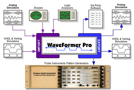
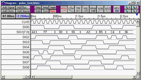
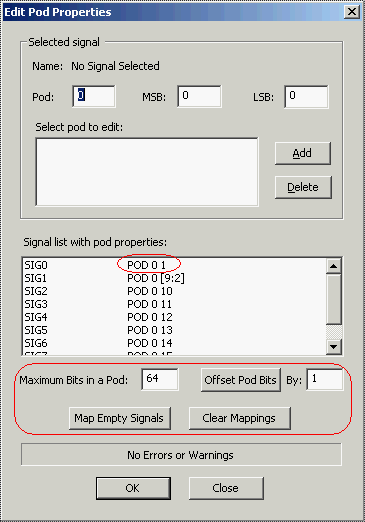
Timing Diagram Editing EnvironmentIn addition to direct translation, WaveFormer can generate stimulus waveforms using a combination of graphically drawn signals, timing parameters that constrain waveform edges, clock signals, and temporal and Boolean equations for describing complex, quasi-repetitive signal behavior. Advanced operations on signals such as time scaling and shifting, and block copy and pasting of signal behavior over an interval of time are also supported. This simple, but powerful environment dramatically eases the labor associate with the generation of complex stimulus. The resulting hardware test benches also have the same functional coverage of the simulation models ensuring that the hardware prototype is adequately tested. Instructions for Creating PI-2005 FilesWaveFormer Pro and TestBencher use a timing diagram define the waveforms for export. Waveforms can be imported from simulation files or drawn in the timing diagram editor. Each timing diagram should contain one clock. The positive edges of the clock will be used as the sampling points for rest of the waveforms. The period of the clock will be output to the PERIOD statement in the PI-2005 file. By default, WaveFormer will use the first clock in the timing diagram as the sampling signal. If you import waveforms from a simulation file you will need to either add a clock or convert the clocking signal to a SynaptiCAD clock by right clicking on the signal name and choosing Signal <=> Clock from the context menu. The PI-2005 requires that waveform values be only 0's and 1's. So the export script converts non-binary waveform values like tri-state into 1's during the export. Also the PI-2005 only supports time units of NS, US, and MS for the PERIOD statement. This means that the display time unit for the timing diagram should be set to one these three values. Data is loaded serially one channel at a time into the PI-2005. The signals in the timing diagram are mapped to the channels in the PI-2005 using the Edit Pod Properties dialog. PI-2005 channels start with #1 and use Pod0. You must setup Pod0 so that the maximum pod bits is 64 and the offset is 1. TestBencher supports repeat loop markers in the export of PI-2005 data. Each repeat loop defines a subpattern in PI-2005 file. The smallest subpattern supported by the instrument is 20 clock units long, so each repeat loop should span at least 20 clock pulses. Repeat loops are ignored by WaveFormer Pro. WaveFormer and TestBencher Pro Instructions
; Generated by TestBencher Pro
LOAD CHANNEL 1 ;(SIG0)
GOTO 0
(111000011100001111000111)
LOAD CHANNEL 2 ;(SIG1[0])
GOTO 0
(001111001111111110000000)
LOAD CHANNEL 3 ;(SIG1[1])
GOTO 0
(001111000000111000001111)
LOAD CHANNEL 4 ;(SIG1[2])
GOTO 0
(111111001111000111111111)

***** More channel code ***********

LOAD CHANNEL 16 ;(SIG8)
GOTO 0
(001110000100001110001000)
DEFINE SP 1 (1-24)
50 BEGIN 1
51 SP 1 * 1
PERIOD 100.00000000000003 NS
PI-2005 Pattern Generator InstructionsThe resulting text file is a series of GPIB commands that can be read directly by the PI-2005 pattern generator. Contact Pulse Instruments, [email protected], for details on custom application development and working directly with the instrument. The exported text file can also be imported into the PI-PAT control software. PI-PAT is the control software and pattern editor for the PI-2005:
For more information about Pulse Instruments PI-2005 pattern generator visit their web site at www.pulseinstruments.com |
|
|