|
|||||||||||||||||||||||||||||||||||||||||||||||||||||||||||||||||||||||||||||||||||||||||||||||||||||
|
|
TestBencher Code Generation ArchitectureTestBencher creates bus-functional models by using a combination of graphical timing diagrams and top-level template files. The graphical timing diagrams are used to define the reusable timing transactions like a PCI bus read cycle or write cycle. The top-level template file defines the sequence in which the timing transactions will be applied to the model under test. The code generation process in TestBencher is an interactive process so it is easy to experiment with different test bench functionality. Each time a timing diagram is saved the code for that transaction is re-generated, so you can watch how the low-level code changes when you add a new graphical element like a sample or a loop.
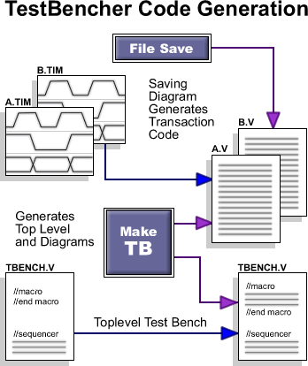
The top-level test bench controls the execution sequence and monitors the status of each timing transaction in the project. It is also the place where the model under test is instantiated and connected to the test bench model. The Make TB button generates the completed test bench model and updates any timing transactions that need it. During code generation TestBencher only changes the code blocks that appear between the macro begin and end statements. Any code that outside the macro blocks is preserved during code generation. The Sequencer ProcessThe sequencer process is the place in the top-level test bench that defines the order in which the timing transactions are applied to the model under test. The sequencer process controls and monitors the execution of the timing transactions. Several tasks are generated for each timing transaction, each with a different execution mode. These tasks are then called from the sequencer process. The task calls are placed sequentially in the order that you wish to have them applied to the model under test.
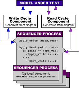
In addition to these task calls, you can also place HDL code in the sequencer. One example where this would be useful is if you wish to place conditions on whether or not a timing transaction is called, or on the parameter values that you wish to have applied. Executing Concurrent Timing Transactions In addition to ordering the timing transactions, the sequencer process is also used to specify the manner in which the timing transactions are applied. Tasks can run in a continuous looping mode or in a run once mode. Also each task can run in either a blocking or a concurrent mode. Generally master bus cycles run once in a blocking mode while global clocks and slave transactions run in a continuous and looping mode. Multiple Test Bench ComponentsTestBencher Pro uses a project file to organize the timing diagram files and top-level template files. These project files have all the information needed to generate an entire bus-functional model. Projects can be included hierarchically in other projects. This allows TestBencher to support multiple test bench component instantiation. Once a test bench has been completed the entire bus functional model that it represents, or project component, can be instantiated in another project.
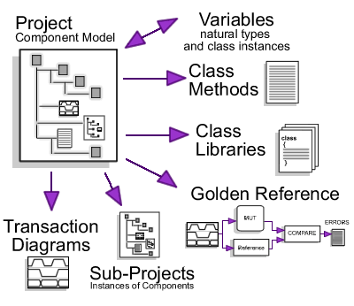
A project that defines a bus-functional model of an SRAM, for example, could be instantiated several times in a higher-level project that is being developed for a microprocessor. The completed microprocessor model could then be instantiated in a project for a video card. This is one way in which TestBencher allows the re-use of test bench components. Verification of devices with multiple ports can also be accomplished using multiple test bench component instantiation. The transactions that would connect to the ports would be instantiated as many times as needed in the higher level test bench. This methodology allows a large test bench to be broken into smaller, self-contained components. Each sub-project can be modified at any time, either stand-alone or while developing the owning project. The properties of the project are always maintained. |
|
|