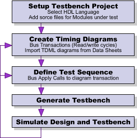
TestBencher Design Flow
TestBencher Pro uses graphical timing diagrams and a top-level template file to generate the test bench
code. The graphical timing diagrams represent reusable bus transactions like a PCI bus read or write
cycle. The top-level template file connects the transactions to the model under test and it defines
how the transactions are applied to the model under test.
Open a Test Bench Project
TestBencher Pro's Project wizard helps you quickly set up the basic project files and settings. The
wizard will prompt for the project name, directory, and language. You can also setup some default settings
like a default clock for cycle based test benches.
Add MUT source files to Project
Once the project is created, you will
want to add the Models Under Test (MUTs) source code
files to the Project window. This will give TestBencher
access to the source code so that it can automatically
extract port and signal information and use it to
generate the test bench.
Create Timing Diagrams and Bus Transactions
TestBencher Pro uses graphical timing diagrams to represent the interface specifications of the bus-functional
model that you are creating (e.g., read cycle, write cycle, interrupt cycle). Timing diagrams are created
using the built in timing diagram editor. The bus functional model code is generated from the waveforms,
samples, markers, and data structures that are contained in the timing diagram. The test bench code
for each bus transaction is regenerated as soon as you save the changes to a timing diagram, so modifications
to the test bench can be tested immediately.
Using timing diagrams you can quickly model common bus activities such as:
-
Driving control signals
-
Sampling and verifying values from the model under test (reporting unexpected values or transitions)
-
Waiting for handshaking signals before completing a transaction
-
Aborting a transaction under a reset condition
-
Models both synchronously clocked (cycle-based) and asynchronous transactions
Optionally Import Diagrams from other Tools
In addition to graphically creating your timing diagram transactions, you can also import them from
other sources. TestBencher Pro supports a variety of file formats for import, including: HP Logic Analyzers,
simulator VCD output, and TDML. Hand coded VHDL and Verilog transactions can also be called directly
from TestBencher's top-level template file. SynaptiCAD recognizes the importance of data transfer between
the variety of tools available on the market and strives to ensure that our products will be able to
communicate with them.
Define Test Sequence
TestBencher uses the sequencer process in the top-level template file to control the order and conditions
under which the transactions will execute. For example, a common sequencer might consist of a state
machine (implemented with a case statement) that calls an appropriate transaction based on data captured
from the model under test during the previous transaction.
Most of the sequencer code is automated using the Apply Transaction dialog to generate the calls
to the bus transactions. TestBencher provides four different subroutine calls for starting a bus transaction.
These subroutine calls are designed to allow you to control how the transaction is applied: one-time
execution, continuous execution, concurrent execution, or continuous and concurrent. There is also an
Abort subroutine that enables the sequencer to stop a concurrently executing transaction.
Generate Test Bench
Once your timing diagram transactions have been created and the transaction sequence has been added
to the template file, simply click the Make TB button to automatically generate your test bench.
This results in expansion of macros embedded in the template file and the generation of any un-saved
timing diagrams. The macro expansion creates the signal and component declarations necessary to finish
connecting up your MUT to the bus transaction models.
The expansion of the template file is a process that can be repeatedly performed as the test bench is
modified. TestBencher does an in-place expansion of the macros, which preserves any code you have added
to the template file. Expanded macro lines are surrounded by specially commented lines that separate
user code from macro-generated code. Only the generated code is overwritten when the Make TB
button is clicked.
TestBencher Pro also supports multiple components and hierarchal design by allowing projects to be included
inside other projects. This method lets you build complicated bus-functional models by designing and
verifying individual components before constructing the finial model.
Simulate The Test Bench
Once the test bench has been generated, the source files for the project are used to simulate the project.
These files can be used either with the Verilog simulator provided with TestBencher (if you are working
in Verilog) or with another Verilog, VHDL, or SystemC simulator. If you are generating OpenVera then
TestBencher can hand the source code files to Synopsys's VERA compiler and then automatically launch
a VHDL or Verilog simulator.
As your test bench executes, a log file will be generated that records the name and time at which each
transaction executes, along with any notifications of expected and unexpected behaviors of the model
under test. You can also view the execution of the transactions graphically in your simulator's waveform
window. Each bus transaction contains a status signal that can be watched to determine the current execution
state of the transaction.
|